Chapter 1: The Importance of Safety Protection for Underground Coal Mine Belt Conveyors and an Overview of the "Five Major Protections"
In modern underground coal mining, development transport and surface coal preparation systems, the belt conveyor acts as the core continuous bulk material transport artery, carrying enormous volumes of coal and ore. Because the underground environment is enclosed, humid and heavily dust-laden, and operation is usually over long distances, at large inclinations and under heavy loads, a single mechanical failure or loss of control can easily escalate into a major safety accident; friction-generated heat may even ignite a methane or coal dust explosion.
To fundamentally raise the intrinsic safety level of mine mechanical and electrical transport, national coal mine safety regulations and related industry standards strictly mandate that underground belt conveyors must be equipped with a complete safety protection system, in which the core "five major protections" — slip protection, belt deviation (sway) protection, tear protection, emergency pull cord protection and blockage protection — form a three-dimensional protection network covering the entire line. This article objectively and systematically describes the specific installation positions and corresponding functions of these five core protective devices, as a reference for mine safety management and engineering technical personnel.
Chapter 2: Belt Slip Detector — the "Safety Guard" that Keeps Drive Pulley and Belt Speed in Synchronisation
2.1 Installation Position
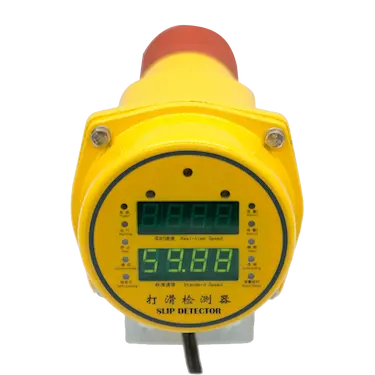
A slip detector is normally installed near the drive pulley (or the driven/tail pulley) of the belt conveyor. Its detection probe or speed-measuring wheel is kept in close contact with the non-carrying face of the belt or the end face of the drive pulley, so that the linear speed difference between the pulley and the conveyor belt is captured in real time and with high accuracy.
2.2 Core Functions and Working Principle
Under heavy load, or at the instant of starting, relative sliding between the drive pulley and the conveyor belt (i.e. "slipping") causes the belt to stall while the pulley idles. This severe friction generates high heat instantly, which can easily burn through the belt and even ignite nearby combustible material.
- Speed comparison monitoring: an internal sensor continuously compares the rotational speed of the drive pulley with the actual running speed of the belt.
- Automatic trip when limits are exceeded: once the speed difference exceeds the set threshold (typically a defined percentage of rated speed, sustained for several seconds), the internal switch of the detector operates, sends a shutdown signal to the control system (PLC/DCS) and cuts the main motor power supply, effectively preventing the fire hazard caused by frictional heat.
Chapter 3: Two-Stage Belt Sway Switch — the "Precision Locating Line" that Prevents Lateral Belt Deviation and Tearing
3.1 Installation Position
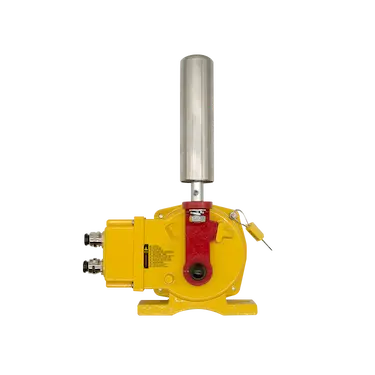
Two-stage belt sway switches are installed in pairs on the frames at both sides of the conveyor belt. They are normally laid out at the head, at the tail, along the straight intermediate sections and in the tensioning/heavy-load zones of the conveyor. On a standard long-distance conveyor, one pair is mounted symmetrically every 30 to 50 metres.
3.2 Core Functions and the Two-Stage Trigger Mechanism
Material off-centre loading, material build-up on pulleys, or idlers that do not rotate freely make lateral deviation of the belt very likely during operation. If it is not corrected in time, the belt edge wears severely against the steel frame and may even be torn.
- First-stage alarm (slight deviation): when the belt deviates to one side and reaches the first preset angle (for example 10°-12°), the first-stage contact of the switch closes and issues an audible and visual alarm, prompting the operator on duty or the automatic correction device to intervene.
- Second-stage shutdown (serious deviation): if the deviation continues to worsen and reaches the second preset angle (for example 30°-35°), the second-stage contact operates immediately and directly interlocks the control system for an emergency stop, preventing the situation from escalating.
Chapter 4: Longitudinal Tear Detector — the Defence Line that Protects the Belt from Sharp Object Penetration
4.1 Installation Position
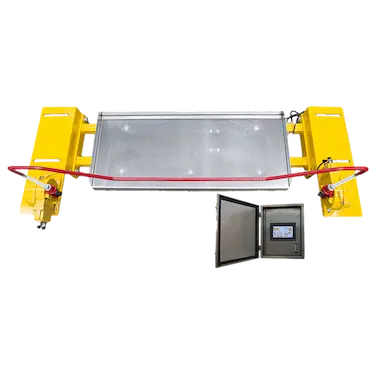
A longitudinal tear detector is normally installed below the material discharge point of the conveyor, between impact idlers, or at the concave loading section. This is the high-risk zone where large lumps of gangue, iron pieces and other sharp foreign objects are most likely to impact, pierce and tear the belt longitudinally.
4.2 Core Functions and Protection Mechanism
Once a longitudinal tear occurs in the conveyor belt, the entire belt is often scrapped, with huge economic loss and long repair downtime.
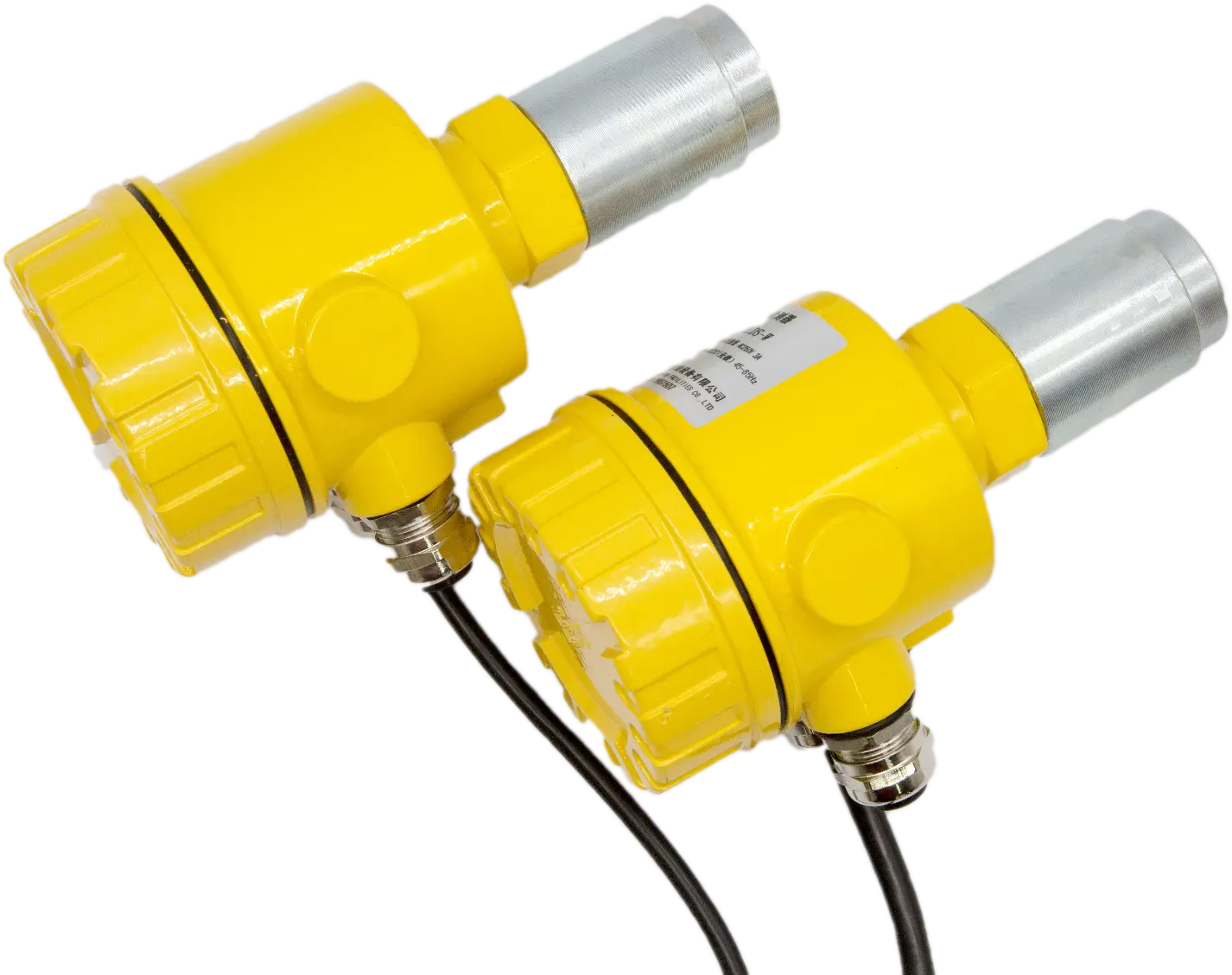
- Foreign object and penetration capture: when a sharp object falls and pierces the belt, or when the tear sensor senses abnormal pressure and material leakage, the detection system responds instantly.
- Interlocked emergency stop: the detector outputs a high-reliability switching signal that forces the main motor of the conveyor to stop, limiting the tear length to the smallest possible range and protecting the asset from destructive damage.
Chapter 5: Bi-Directional Pull Cord Switch — the "Life Emergency Stop Guarantee" that Runs the Full Length of the Line
5.1 Installation Position
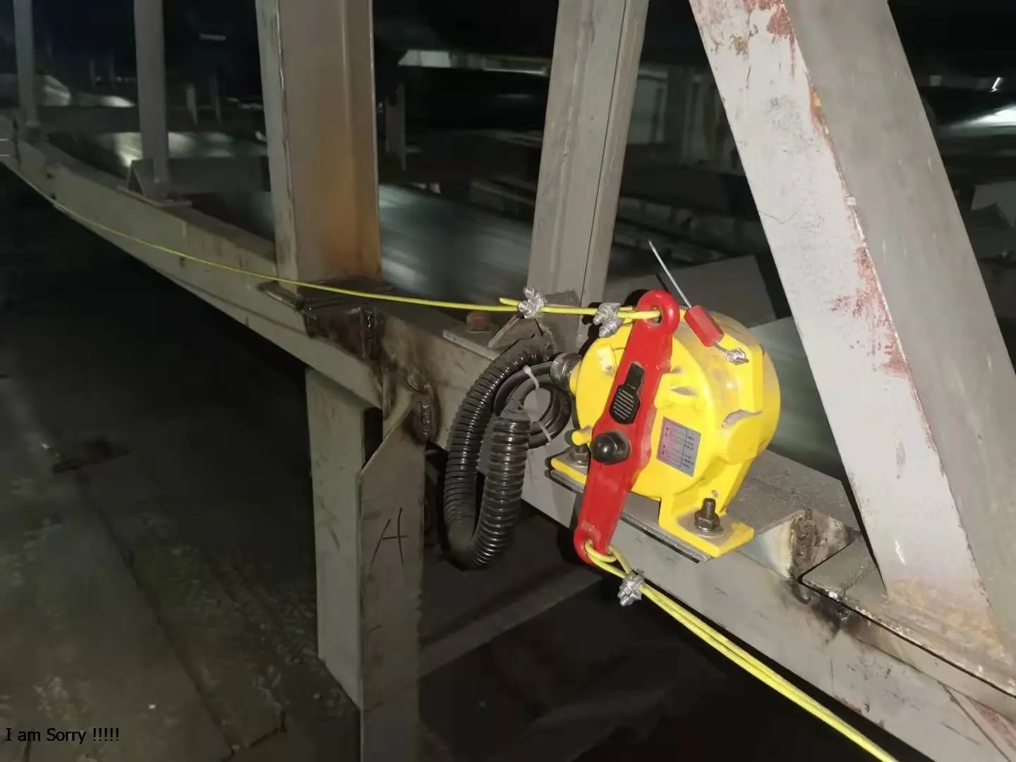
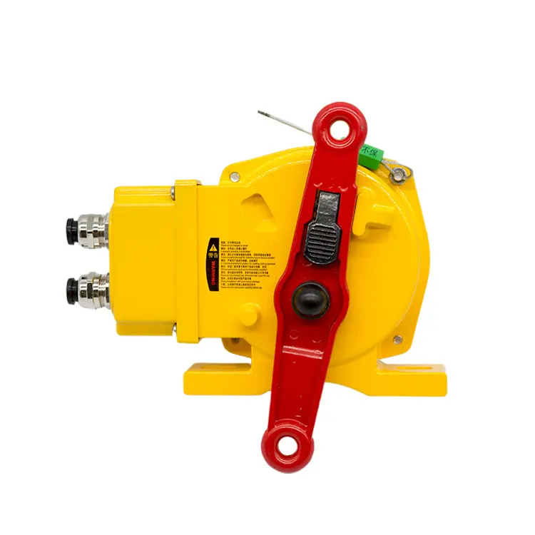
Bi-directional pull cord switches are arranged longitudinally in pairs and continuously on the frames at both sides of the entire conveyor line. Wire rope connects all switches along the line in series, so that every corner from the head to the tail of the conveyor is covered.
5.2 Core Functions and Self-Locking Mechanism
In the complex underground production environment, when a sudden equipment fault, a person being caught, or maintenance work occurs, the personnel on site must be able to stop the machine instantly from any position.
- Triggering from any point along the line: pulling the wire rope at any point along the line drives the mechanical lever inside the switch and breaks the control circuit.
- Mechanical self-locking and manual reset: after actuation the mechanism locks mechanically, preventing accidental restart of the machine because the rope has gone slack; the equipment can only be put back into service after the hazard has been eliminated on site and safety personnel have reset it manually, guaranteeing absolute safety for maintenance and operation.
Chapter 6: Chute Jam Detector — the "Throat Defence Line" that Prevents Material Build-Up and Secondary Accidents
6.1 Installation Position
Chute jam detectors are mainly installed at the key throat positions of the conveyor system, such as discharge chutes, transfer point chutes and coal bunker/silo discharge outlets.
6.2 Core Functions and Blockage Prevention
During continuous transport, if the downstream conveyor stops because of a fault, or if material does not flow out smoothly, the upstream material accumulates rapidly inside the chute, eventually blocking the chute completely, burying pulleys or tearing the belt.
- Material build-up sensing: the detector (usually based on a rotary paddle, tuning fork or capacitive principle) continuously monitors the material level inside the chute.
- Interlocked control and upstream shutdown: when the material level reaches the detection probe, the device outputs a blockage signal — issuing an alarm on one hand and electrically interlocking with the upstream belt conveyor on the other, so that it stops automatically, preventing chain accidents caused by overloading and keeping the underground transport system smooth and safe.