
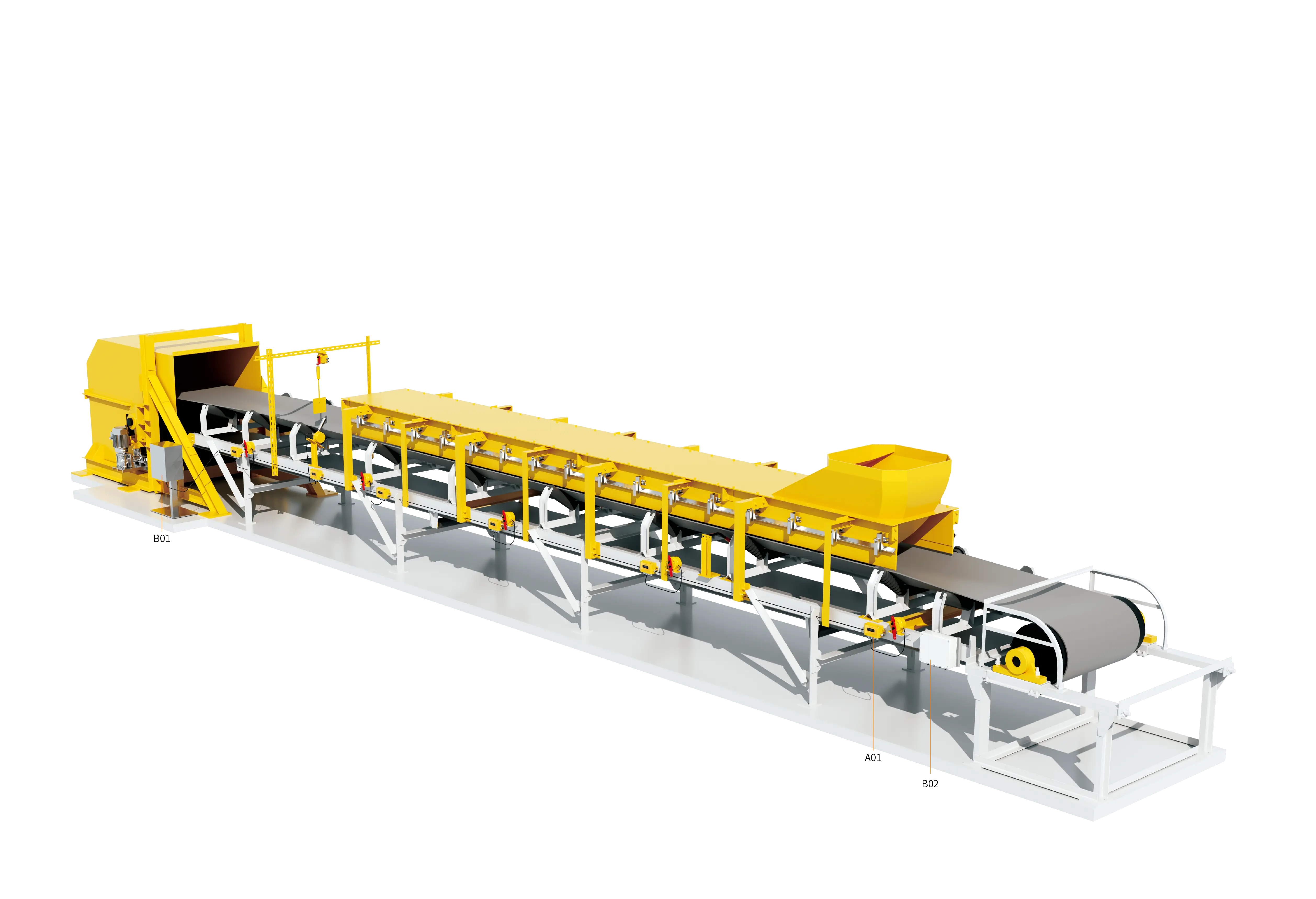
In large open-pit coal mines, deep underground mines, large thermal power bases, cross-regional ore transport trunk lines, and coastal deep-water bulk cargo terminals, overland and tunnel-type long-distance belt conveyors (Overland / Long-Distance Belt Conveyor) are comprehensively replacing traditional short-haul rail and truck transport. Such modern large-scale conveying equipment typically achieves a single-unit haul distance of 3 to 15 kilometers or more, and is characterized by large throughput, high belt speed, distributed multi-motor drives (head-tail coordination or intermediate multi-point drives), and complex, variable terrain along the route.
As the conveying distance extends exponentially, the number of safety protection sensors installed along the entire conveyor line (such as emergency pull-cord switches along the route, two-stage deviation switches, slip detectors, tear sensors, and material level probes) reaches dozens or even hundreds of groups. Under the traditional centralized control mode, hundreds of sensors must be wired "point-to-point" back to the distribution room or central control room through multi-core control cables. Long-distance multi-core laying not only results in enormous cable investment and extremely cumbersome construction wiring, but also exposes serious line-loss voltage drops, strong electromagnetic interference false alarms, and the fault-troubleshooting blind spot of "knowing that an alarm has occurred but not which specific device has actuated" in actual operation.
To achieve intrinsic safety, rapid self-healing, and efficient less-manned/unmanned operation of ultra-long conveying lines, a remote integrated control system based on distributed fieldbus communication technology and digital address encoding has become the core hub of modern bulk material storage and transport engineering. The system runs through the entire line via a minimalist two-wire or fiber-optic network, seamlessly connects the massive number of sensors along the route to the central control host computer, and realizes millisecond-level acquisition of equipment status across the whole line and precise spatial localization of fault points.
I. Four Major Bottlenecks of Traditional Hardwired Control for Long-Distance Conveyors
To understand the advantages of fieldbus remote control systems, it is first necessary to analyze the technical limitations exposed by the traditional point-to-point hardwired mode under long-haul operating conditions:
1. Construction Laying and Cable Material Costs Expand Exponentially
If a 10-kilometer conveyor line is equipped with 200 sets of bidirectional pull-cord switches and deviation switches along its route, using traditional multi-core control cables to route them back to the control cabinet not only consumes tens of kilometers of expensive shielded copper cable, but also requires the laying of extensive cable trays and galvanized conduits along the way; the cost of pipeline installation and civil engineering can even be several times higher than that of the protection devices themselves.
2. Severe Long-Distance Signal Attenuation and Power-Frequency Electromagnetic Interference
In high-impedance loops spanning several kilometers or even more than ten kilometers, conventional control signals such as DC 24 V will produce significant voltage drops, preventing remote relays from picking up reliably. At the same time, high-frequency electromagnetic pulses generated by high-voltage power grids, high-power variable-frequency motors, and high-altitude lightning induction along the route are easily coupled into multi-core parallel cables, inducing large-area false signal triggering or breakdown of control ports.
3. Slow Spatial Fault Localization and Huge Unplanned Downtime Losses
In a traditional series loop (hard relay normally closed loop), as long as any pull-cord switch along the route is pulled or a deviation action occurs, the main control cabinet can only receive an ambiguous switching signal indicating "loop broken, shutdown occurred," and cannot determine which device at which kilometer the fault occurred. Inspection personnel often need to ride bicycles or walk along several kilometers of the route to inspect and reset devices one by one; troubleshooting and shutdown investigation often take several hours, severely constraining the comprehensive throughput efficiency of the entire line.
4. Inability to Realize Bidirectional Digital Interaction and Health Status Perception
Traditional switches can only transmit a single binary "on/off" information, and cannot return the device installation status, ambient temperature and humidity, contact oxidation degree, or communication link health. They are even less capable of issuing reverse self-test or local drive commands from the central control room to specific field units.
II. Three-Layer Topology Architecture and Working Mechanism of the Bus-Based Remote Control System
In view of the characteristics of long-distance continuous conveying, modern remote control systems generally build a three-layer three-dimensional network architecture consisting of a "field encoding and sensing layer," a "digital communication and repeater layer," and a "central control host computer monitoring layer":
1. Field Intelligent Address Encoding Unit (Bottom-Layer Digital Node)
The system integrates or externally attaches an independent address encoding module (Address Encoding Unit) to each sensor arranged along the route (pull-cord switch, deviation switch, slip or tear probe, etc.).
- Unique physical identifier: Each encoding module has a line-wide unique digital ID identification code. A micro-power processor and self-diagnostic circuit are integrated inside the module to monitor the state changes of external switch contacts and the continuity of the loop in real time.
- Digital packet upload: When a switch is triggered or a short-circuit/open-circuit fault occurs, the encoding module packages the switch action status and its own unique address code into a highly noise-immune digital message and sends it upward through the shared communication bus.
2. Transmission and Repeater Unit (Long-Distance Anti-Attenuation Repeater Network)
- Non-polarized two-wire bus transmission: Hundreds of encoding nodes in the field are connected in parallel to one or two pairs of high-strength flame-retardant communication buses (or twisted-pair optoelectronic hybrid cables) in a tap-off manner, completely replacing hundreds of multi-core cables. The bus generally supports non-polarized arbitrary topology wiring, greatly reducing the risk of wiring errors during construction.
- Long-distance repeater isolator (Repeater Unit): When the conveying distance exceeds the standard communication limit of copper cable (for example, a single section exceeds 3 to 5 kilometers), repeater amplifiers or fiber-optic converters (optical transceivers) are connected at predetermined intervals along the line. The repeater not only regenerates and amplifies the communication signal waveform, but also provides bidirectional electrical isolation of several thousand volts, cutting off long-distance ground loops and isolating lightning surges.
3. Integrated Protection Instrument and Communication Substation (Edge Parsing and Safety Interlocking)
The integrated protection instrument (Integrated Protection Instrument) installed in the field distribution room or drive station serves as the centralized gateway of the fieldbus.
- High-speed multi-point polling: A high-speed polling or interrupt event-driven mechanism is adopted to complete the cyclic self-test and status scanning of hundreds of detection nodes across the entire line within an extremely short period (usually less than 50 ms).
- Local hardware safety interlocking: The integrated protection instrument has an independent high-speed microprocessor and hardware output relays. Once an emergency stop or severe deviation command from any node is received, there is no need to wait for the host computer's response; the substation can directly cut off the main motor control contactor on site, ensuring the highest priority level of safety protection.
4. Host Computer SCADA Monitoring Unit (Centralized Visualization and Big Data Hub)
The host computer control system located in the central control dispatch room is connected in real time with the integrated protection instruments of each section through standard industrial Ethernet (mainstream protocols such as Modbus TCP, Profinet, and EtherNet/IP).
- 1:1 spatial topology visualization of the entire line: The large monitoring screen visually presents a dynamic panoramic model of the conveyor extending for several kilometers.
- Meter-level precise positioning display: Once a node actuates, the host computer interface immediately pops up a warning red box, precisely indicating that the action occurred at "KM 4.250, No. #086 bidirectional pull-cord switch," and automatically links to the industrial surveillance camera image of the corresponding area.
III. Analysis of the System's Core Units and Key Hardware Functions
A highly reliable remote control system for long-distance belt conveyors is mainly composed of the following four functional units working together:
1. Address Encoder (Built-in/External Type)
- Core function: Convert conventional passive dry contact (SPDT/DPDT) signals into bus digital signals, and provide quiescent operating current and node heartbeat packets to the bus.
- High-protection design: The enclosure protection rating is not lower than IP65/IP67, adapting to open-air rain and snow, extreme cold and high temperatures, as well as coal dust, oil pollution, and corrosion along the route; it features automatic anti-jitter filtering and broken-line self-diagnosis.
2. Signal Repeater and Fiber-Optic Redundant Ring Network Terminal
- Core function: Extend the physical communication distance and compensate for the line loss of the transmission medium. It has automatic single-bus disconnection detection and ring network self-healing capabilities.
- High-reliability guarantee: Supports dual-bus active/standby redundancy or a closed ring network. When any point in the middle is cut by an external force, the repeater unit automatically switches the communication direction within milliseconds, ensuring no blind spots in communication for nodes on both sides of the break point.
3. Integrated Protection Instrument / Control Substation
- Core function: Responsible for bus power supply management, signal modulation and demodulation, protocol conversion, local digital/LCD display, and execution of emergency stop interlocking logic.
- Parameter calibration and local interaction: Supports direct on-site setting of deviation alarm delay and slip alarm threshold ratio, and records the most recent hundreds of historical action events with timestamps.
4. Remote Host Computer Control Software
- Core function: Centralized monitoring of the entire line, display of belt speed and load curves, analysis of motor temperature and vibration trends, audible and visual push of fault alarms, export of statistical reports, and data penetration and interconnection with the mine's plant-wide integrated dispatching automation system (MES/ERP).
IV. Technical and Economic Comparative Analysis of Fieldbus Communication Systems and Traditional Hardwired Solutions
To comprehensively evaluate the application benefits of this technology in large-scale engineering, the table below provides a systematic quantitative comparison of the key indicators of the two control modes:
| Evaluation Dimension and Indicator | Traditional Multi-Core Cable Hardwired Mode | Digital Bus-Based Remote Control System | Assessment of Engineering, Technical, and Economic Differences |
|---|---|---|---|
| Cable Consumption and Laying Engineering | A multi-core cable is routed every few dozen meters; 10 km requires dozens of kilometers of control cable | Only one pair of twisted-pair communication cable or fiber-optic cable is needed for the entire line, with tree or bus-type nearby tap connections | Saves 70% to more than 85% of cable material and conduit/tray installation engineering costs |
| Fault Localization Accuracy | Only the loop disconnection is known; accuracy is "the entire conveyor" (a 5–10 km blind zone) | Precise localization to the specific fault point ID and spatial physical mileage (meter-level accuracy) | Troubleshooting and on-site reset time is shortened from 1–2 hours to within 5 minutes |
| Communication Transmission Distance and Anti-Attenuation Capability | High copper resistance; DC signals attenuate severely beyond 3 km and are susceptible to power grid electromagnetic harmonic interference | Digital differential or fiber-optic transmission, which can be stably extended beyond 15 km after repeater amplification | Completely eliminates the risk of controller false alarms and refusal to operate caused by long-line level attenuation |
| System-Wide Status Polling Cycle | No digital polling, but the distributed capacitance and inductance of long conductors may cause signal filtering lag | High-speed industrial communication protocols are used; the polling update cycle of hundreds of nodes across the line is less than 50 ms | Response speed fully meets the safety response regulations for various emergency stops of ultra-long conveyors |
| Communication Redundancy and Link Self-Healing | A single-point disconnection disables the entire loop and stops the system; tracing the line is extremely time-consuming and cumbersome | Supports ring networks and dual-bus redundancy; a single-point disconnection is self-healed without interrupting communication | Greatly improves the operational availability of complex long-distance industrial trunk lines in harsh environments |
| Later System Expansion and Node Maintenance | Adding sensors requires new long-distance cabling from the control room, with extremely high modification costs | The bus can be stripped open at any position along the route to connect a new encoder in parallel, achieving plug-and-play | Greatly facilitates the operating condition in which the belt conveyor is continuously extended as the mining face advances |
V. Multi-Drive Coordination and Millisecond-Level Interlocking Control Logic for Long-Distance Systems
For ultra-long conveying systems equipped with multiple drive stations (for example, three high-power motors at the head, two auxiliary drives at the tail, or an intermediate unloading drive), the remote control system also undertakes the important tasks of multi-motor starting sequence balancing and full-line safety interlocking:
- Distributed soft starting and torque balance coordination Before the conveyor starts, the host computer and each substation automatically traverse the pull-cord, deviation, tear, and bin level signals across the entire line to ensure a fault-free ready state; subsequently, starting curve commands are issued to the variable-frequency drives of each drive station through the high-speed bus, precisely coordinating the starting sequence and tension build-up speed of each drive pulley motor, eliminating the huge dynamic tension shock wave generated by the belt across a span of several kilometers, and preventing the belt from being broken.
- Three-level response interlocking emergency stop control sequence
- Level 1: Millisecond-level local hardware cutoff (< 50 ms) When the pull-cord emergency stop switch at any position actuates, the address encoder sends an emergency stop interrupt message. The integrated protection instrument hard-trips the main drive circuit within 50 milliseconds and simultaneously broadcasts an instantaneous braking command to each drive substation, ensuring that the heavily loaded belt decelerates and stops smoothly within the shortest coasting distance.
- Level 2: Cascaded shutdown of the upstream and downstream conveying process chain The main protection instrument synchronously sends a shutdown interlocking signal to the feeder and the upstream feed belt, preventing severe material blockage and machine burial accidents in the transfer chute caused by continued upstream feeding.
- Level 3: Central control precise positioning and intelligent screen dispatching The host computer pops up the action position and the equipment type in real time (for example, "KM 6.780 #132 deviation action"), links the PTZ camera to turn to the fault site, and saves the event record to disk, strictly preventing blind forced remote secondary reset and restart before the cause is identified.
VI. On-Site Engineering Wiring, Lightning Protection, Anti-Interference, and Long-Term O&M Specifications
To ensure that a remote control system covering several to more than ten kilometers operates stably year after year, on-site engineering construction and maintenance must strictly follow the following regulations:
- Physical isolation of the bus and avoidance of strong current: The communication bus must be laid in dedicated galvanized steel conduits or high-protection fire-resistant cable trays. It is strictly prohibited to lay it in the same layer or the same trench as 6 kV/10 kV high-voltage cables or the output power cables of high-power variable-frequency drives. When crossing, it must cross vertically at 90 degrees with a spacing of not less than 300 mm.
- Multi-level lightning protection and equipotential grounding system: Because long-distance open-air conveyor structures are located in lightning-prone belts, each communication substation, repeater, and incoming/outgoing line port must be equipped with dedicated industrial-grade high-speed surge protective devices (SPD); the shielding layer of the communication line must follow the principle of strict single-end grounding, preventing uneven grounding potentials in different areas over several kilometers from forming parasitic ground loops that burn out modules.
- Node address management and periodic inspection: On-site maintenance personnel are strictly prohibited from arbitrarily swapping or repeatedly setting the DIP switches (or electronic IDs) of the encoders; every quarter, the attenuation of the communication link and the optical power margin of the optical fiber across the entire line should be tested, and pull tests should be carried out on samples of the pull-cord switches along the route to verify that the spatial correspondence between the host computer message address and the physical field equipment is 100% absolutely consistent.
Through the deep integration of digital address encoding, highly noise-immune fieldbus communication, and intelligent SCADA monitoring networks, modern long-distance belt conveyors have achieved a major technological leap from "blind-man-and-elephant-style extensive operation and maintenance" to "holographic perception and meter-level precise localization," building an extremely robust safety nerve center for large-scale bulk material transfer in heavy industry.
Learn about the bus communication and remote control solution for long-distance belt conveyors