
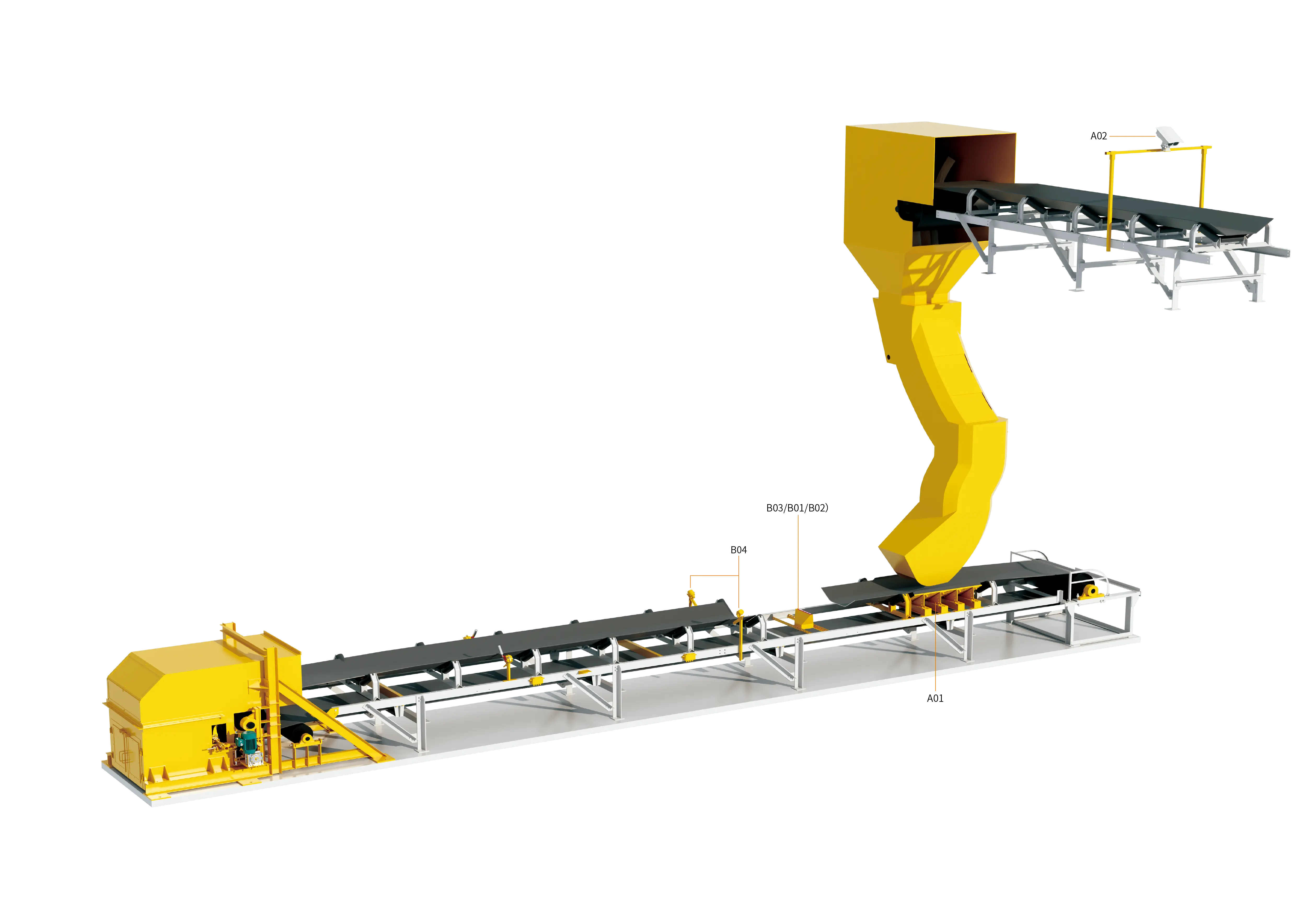
In underground coal mines and coal preparation plants, metal mining and mineral processing, coal handling systems of thermal power plants, large bulk port terminals, and heavy industrial scenarios such as cement and metallurgy, belt conveyors are the core lifeline that guarantees continuous, high-capacity transfer operations for bulk granular materials. Within the entire conveying equipment set, the high-strength heavy-duty conveyor belt (whether a steel cord conveyor belt or a high-polymer multi-ply fabric-core conveyor belt) not only bears the full material load and traction power, but its asset value also typically accounts for 30% to 50% of the total initial equipment investment of the entire conveyor.
However, under continuous high-load operating conditions, because material sources are complex and the impact kinetic energy at the loading point is enormous, the conveyor belt constantly faces the fatal threat of penetrating puncture and longitudinal tear. Once a sharp foreign object pierces the belt and is jammed by the conveyor frame, under the powerful traction force of the drive motor, the conveyor belt can be “ripped open” and torn for hundreds of meters or even several thousand meters within just a few minutes or even tens of seconds. Such a catastrophic accident not only scraps the entire expensive belt and causes large-area material spillage and spread, but is also accompanied by unplanned full-line shutdowns of several days to several weeks, resulting in incalculable economic losses and hidden dangers to production safety.
For a long time, industrial sites have often fallen into the misconception of “passive response” to longitudinal tears — relying only on a single downstream tear sensor for post-event shutdown, so that by the time the detector actuates, the belt has often already been torn for tens of meters; while relying solely on the discharge hopper to block objects cannot cope with the penetration of tiny sharp iron pieces. Therefore, building a three-dimensional full-life-cycle comprehensive protection system that covers “front-end impact buffering and foreign object interception (pre-event prevention)” and “full-section high-speed multi-dimensional online monitoring (in-event millisecond-level interlocking)” is the only technical path to achieving intrinsic safety and intelligent operation and maintenance of bulk material conveying systems.
1. Physical and Mechanical Mechanisms and Core Causes of Conveyor Belt Longitudinal Tears
A belt tear is by no means a simple wear failure; it is a sudden mechanical damage process that integrates high stress concentration, mechanical puncture and tearing, and dynamic-load fatigue shear. In actual operating conditions, the root causes that induce longitudinal tears can be summarized in the following four typical scenarios:
1. High-drop sharp foreign object puncture and extrusion jamming at the loading point
This is the most common and most destructive form that causes long-distance tears. Large discarded iron objects mixed in during excavation or crushing (such as high-manganese steel plate hammers broken off from crushers, shearer picks, mining support anchor bolts, wire mesh and I-beam fragments), or extremely hard and sharp large gangue blocks, fall at high speed from transfer chutes several meters high. When these sharp objects pierce the belt surface at a specific acute angle and penetrate the belt core, their lower ends are very easily rigidly jammed by the idler support frame below, the lower crossbeam at the outlet of the transfer hopper, or the edge of the skirtboard. At this moment, the belt running at high speed forcibly slides relative to the jammed and fixed blade, and the blade rapidly splits the entire conveyor belt lengthwise like a sharp knife.
2. Loosening and falling off of transfer chute liners and fatigue fracture of structural components
The inner walls of transfer chutes and skirtboards are permanently lined with high-hardness wear-resistant metal or ceramic liners. Under frequent heavy material impacts and vibrations, if the liner fixing bolts fatigue and break, welds crack, or liners fall off, the upturned sharp corners of the hard liners and the fallen wear-resistant steel plates directly insert into the belt working surface, forming a man-made “scraper” that causes penetrating tears of the belt.
3. Large material block extrusion, embedding and material back-pressure
When conveying large raw coal with high moisture content or sticky ore, large blocks are easily trapped in the tiny gap between the skirtboard and the belt. Under the continuous running friction of the belt, the embedded object generates an extremely large downward localized concentrated pressure, instantly destroying the belt cover rubber and cracking the carcass. In addition, material back-pressure to the head discharge pulley caused by chute blockage and accumulation, with material being crushed between the pulley and the return run of the belt, will likewise lead to severe belt extrusion and bursting.
4. Belt edge deviation scraping and joint fatigue crack propagation
When the conveyor suffers serious mistracking, the belt edge is rigidly scraped against the frame structure, causing the edge rubber to peel off and expose the edge steel cords or canvas plies. Once the exposed steel cord joint hooks onto fixed angle steel or idler supports along the line during operation, the pulling stress will tear at a right angle into the interior of the belt; at the same time, aging and upturned teeth of the mechanical belt joint (belt fastener) or delamination of the vulcanized joint will also induce tears to propagate rapidly lengthwise along the damaged crack under external impact.
2. Tear Prevention System: Front-End Protection and Energy-Absorbing Interception (Unit A)
Truly high-level safety protection must resolve risks before they occur. By deploying “tear prevention units” in the material energy release zone and high-risk loading sections, more than 80% of the probability of foreign object puncture can be eliminated at the source:
1. High-damping heavy-duty impact bed unit at the loading point (loading kinetic energy dissipation and seamless support)
The loading zone of a traditional conveyor usually adopts a buffering idler structure, but there must inevitably be a physical gap of 100 mm to 200 mm between idlers. Once a sharp object pierces the belt, it will sink deeper and deeper into the suspended gap between the idlers, and finally be jammed on the next row of idler frames, resulting in a tear.
- Structural advantages: The heavy-duty impact bed is formed by composite support bars of an ultra-high molecular weight polyethylene (UHMWPE) smooth surface layer and a high-elasticity natural energy-absorbing rubber layer, arranged side by side and tightly packed. It provides a completely continuous and flat “surface contact support” for the belt in the loading zone, thoroughly eliminating the suspended dead zones between idlers.
- Protection mechanism: The UHMWPE surface layer has an extremely low friction coefficient, so falling sharp objects cannot find a purchase to become jammed, but instead slide away along the direction of travel; the underlying high-density rubber has excellent impact absorption performance and can absorb and eliminate more than 90% of the vertical impact kinetic energy of falling large ore blocks, preventing the belt carcass from being punctured and broken by localized overload impact.
2. Mechanical and electromagnetic multi-stage foreign object interception unit (pre-cleaning of high-risk tramp iron)
- Blocking and sorting at the discharge port: Multi-stage heavy-duty damping hanging foreign object curtains or comb-shaped flow guide fingers are installed inside the transfer chute to comb the falling material flow in layers, forcibly changing the posture of long anchor bolts or plate-shaped iron pieces so that they slide down flat and avoiding vertical stabbing of the belt.
- Front-end strong iron removal and metal detection: A self-unloading super-strong electromagnetic iron remover or permanent magnet iron remover is reasonably connected in series on the upstream belt section, and a high-sensitivity all-metal detector is arranged in front of the transfer point. When non-magnetic or deeply buried high-risk foreign objects are sensed, the system can issue an early warning in advance or start the diversion flap, completely rejecting large iron objects outside the loading zone.
3. Tear Detection System: Multi-Dimensional Online Real-Time Capture and Instantaneous Braking (Unit B)
Even with rigorous physical protection, the possibility of extremely fine sharp objects piercing through under extreme operating conditions cannot be completely ruled out. This requires a “tear detection unit” with high sensitivity and millisecond-level response to complete identification and braking at the very moment the belt is pierced, strictly limiting the tear length to the smallest possible range:
1. Cable-press type and pulley-displacement tear detection unit (mechanical penetration force-sensitive detection)
The cable-press type longitudinal tear detector is the physical monitoring device with the most mature technology and the highest environmental tolerance in the industrial field, usually arranged closely between the buffer idlers behind the loading section or on the lower surface of the belt.
- Working mechanism: One or more highly flexible stainless steel wire ropes are tensioned transversely below the lower surface of the conveyor belt, and the end of the rope is connected to a high-precision microswitch interlocking mechanism. When a sharp blade or hard gangue penetrates the belt and protrudes from the belt bottom, the high-speed protrusion moving with the belt will forcibly press down the transverse wire rope or strike the pulley mechanism.
- Response action: At the moment the wire rope is pressed, it overcomes the internal spring tension and displaces, driving the microswitch to actuate and instantly outputting one or more sets of dry contact signals. The bidirectional cable-press structure can not only sense the vertical penetrating pressure, but also capture oblique dragging external forces, achieving actuation without dead zones.
2. Material leakage/tear force-sensing detection unit (capture of material leakage characteristics)
When the conveyor belt suffers longitudinal penetrating damage or cracks, the fine powdery materials and small particles on the carrying surface will rapidly leak downward along the penetrating cracks.
- Working mechanism: A dedicated receiving chute or leakage tray is installed below the return channel steel of the carrying strand, and a weight sensor or force moment balance mechanism is arranged below the tray.
- Response action: When the belt is intact, no material accumulates on the receiving plate; once local cracking causes continuous leakage, the dynamic load generated by the accumulation of falling material exceeds the set threshold, and the force sensor immediately triggers the power-off interlock, avoiding long-term expansion of hidden micro-cracks that would lead to full-section tearing.
3. Machine vision and AI image edge defect monitoring unit (non-contact intelligent optical inspection)
With the advancement of industrial digitalization, intelligent detection technology based on machine vision and deep learning is becoming an important defense line for high-end bulk material conveying lines.
- Technical configuration: On the lower surface of the conveyor belt or on the clean section after unloading, dust-proof and explosion-proof high-speed line-scan industrial cameras and special laser structured light auxiliary systems are installed.
- Analysis algorithm: The camera continuously captures high-speed images of the non-working surface of the belt, and the AI edge computing unit performs real-time deep semantic segmentation and feature extraction on the belt surface texture. The system can automatically identify, at millisecond level, the scratch depth, abnormal perforations, longitudinal cracks, local bulging tears and edge tearing burrs on the lower surface of the belt. Depending on the severity level of the defect, the system can automatically output graded warnings or drive the relay to trip and stop instantly.
4. Comparison Table of Technical Characteristics and Applicable Scenarios of Prevention and Detection Units
To help engineering design and production operation and maintenance personnel reasonably match system configurations according to on-site material characteristics, the following table systematically summarizes the technical parameters of mainstream tear protection and detection units:
| System Unit Category | Core Technical Principle | Key Protection Functions and Action Response | Optimal Installation Location | Typical Applicable Industrial Conditions |
|---|---|---|---|---|
| Heavy-duty impact bed unit | High-rebound rubber + UHMWPE surface layer full-section energy absorption | Absorbs vertical drop impact kinetic energy and thoroughly eliminates puncture dead zones in idler gaps | The entire section of the direct-drop receiving area of each stage of transfer chute | High-drop heavy-load loading points for metal ore, large raw coal, coke, etc. |
| Cable-press tear detector | Penetrating puncture mechanically presses down the wire rope to trigger a highly sensitive explosion-proof microswitch | Senses sharp foreign objects protruding from the belt bottom within milliseconds and enforces mechanical tripping | Below the conveyor belt within 2 to 5 meters behind the receiving point of the loading zone | Harsh, high-dust, humid continuous conveying trunk lines in heavy industry |
| Leakage/tear sensing unit | Gravity accumulation torque sensing of material leaking through the penetrating crack triggers a switching value | Early dynamic sensing of leakage through fine cracks to prevent slow tear damage | Suspended area at the bottom of the belt carrying surface immediately behind the loading section | Conveying lines for fine-grained mineral powder, pulverized coal, cement raw meal and other easily leaking materials |
| Vision AI tear detection unit | High-speed industrial line-scan camera + structured laser scanning + deep learning image algorithm | Real-time quantification of surface scratches, penetrating holes and crack edges with no mechanical wear | Clean return section of the conveyor belt and the straight visible section at the outlet of the drive pulley | Long-distance pipe conveyors or heavy-duty main conveying lines with high automation requirements and high belt speed (≥3.15 m/s) |
| Edge damage detection device | Belt edge mistracking folding or burr scraping pushes the probe wheel to deflect and trigger | Monitors local edge damage and delamination tearing of the belt edge to prevent longitudinal propagation from the edge | Head discharge pulley, tail pulley and sections along the line prone to mistracking | Various long-distance cross-country conveyors and large-inclination belt lifting systems |
5. Three-Dimensional Hierarchical Interlocking Closed Loop of “Pre-Event Prevention + Millisecond-Level Instantaneous Power Cut-Off”
Deeply integrating the front-end prevention units and multi-dimensional detection units into the on-site PLC/DCS control system can build a well-structured full-process interlocking protection closed loop:
- Level 1: Source kinetic energy dissipation and foreign object interception (passive normal defense) After the material is combed through the chute and intercepted by the iron removal equipment, it falls into the impact bed area. The high-strength impact bed reduces the loading impact stress by more than 80%, and uses the smooth low-resistance surface to force occasional penetrating foreign objects to slide away along the belt's forward direction, avoiding standing upright and stabbing to death in structural dead corners.
- Level 2: Early identification of abnormal states and deviation correction warning (dynamic light-load self-healing) When the vision detection or edge detection probe captures shallow scratches, local small cracks or slight edge wear on the belt surface, the system determines it as a non-penetrating hidden danger. The central control system automatically records the spatial coordinates (mileage positioning) of the defect on the entire belt and highlights it in red on the monitoring screen, notifying maintenance personnel to focus on inspection during the next planned shutdown, avoiding blind unplanned emergency stops that affect continuous output.
- Level 3: Millisecond-level trip and power cut-off upon penetrating puncture (hard interlock hard protection bottom line)
When the cable-press or tear detection probe senses foreign object penetration or a sudden change in transverse tension, the detection device directly connects in series and opens the main motor contactor coil circuit through a highly reliable normally closed (NC) hard contact, and at the same time sends a highest-priority emergency stop interrupt signal to the PLC.
- The system forcibly cuts off the drive motor power within 0.1 seconds and cooperates with the frequency converter and heavy-duty mechanical disc brake to implement emergency pressurized strong braking.
- The interlocking control system stops all upstream feeders and feeding belts synchronously with nanosecond-level delay, completely eliminating inertial coasting drive, and controlling the originally devastating tear accident of hundreds of meters within the initial range of a few meters.
6. On-Site Standardized Installation Specifications and Long-Term Operation and Maintenance Management Guidelines
To ensure that the tear prevention and detection system remains 100% sensitive and reliable over the long term, engineering installation and daily maintenance must strictly implement standardized operating procedures:
- Scientific calibration of installation positioning and clearance:
- The no-load clearance between the detection rope of the cable-press tear detector and the bottom surface of the conveyor belt must be precisely tuned, usually maintained between 20 mm and 30 mm. If the clearance is too large, fine blades cannot touch the sensor; if the clearance is too small, the normal sag and bounce of the belt under full load may cause severe false alarms.
- The mating clearance between the impact bed and the skirtboard should be kept uniform and smooth, and a “wedge-shaped material clamping gap” that is narrow at the front and wide at the back must be strictly prohibited.
- Regular manual practical simulation and function verification:
- Every week, combined with the shutdown maintenance window, a dedicated safety officer must manually press the cable-press linkage or pull the wire rope to check whether the console stop indicator light and the motor power-off circuit action are sensitive and reliable, eliminating mechanical rusting or wiring oxidation failure of switch contacts caused by long-term disuse.
- Maintenance of the surface cleanliness of sensing components:
- The protective cover and transparent window of the vision AI detection unit must be equipped with regular automatic compressed air blowing dust removal or water washing and scraping devices, to prevent floating coal dust and water vapor condensation on site from contaminating the lens and causing optical misjudgment.
- Regularly remove the hardened material accumulated around the cable-press mechanism and the receiving tray to ensure that all force-bearing moving joints rotate freely and the springs have abundant self-resetting elasticity.
Through the scientific implementation of loading buffering and foreign object interception at the process source, supplemented by highly sensitive multi-dimensional online mechanical and visual sensing, industrial bulk material conveying systems can establish an indestructible safety defense line and completely eliminate the industry pain point of longitudinal tearing, which is extremely harmful.
Learn about the conveyor belt tear prevention and detection system solution