
In heavy-industry fields such as underground coal mining and coal preparation, metal mine crushing and ore dressing, coal conveying trunk lines of thermal power plants, cement clinker preparation, and bulk cargo transshipment at ports, belt conveyors are the core artery that sustains continuous operation of the entire production system. In large conveying installations, high-strength heavy-duty conveyor belts (whether flame-retardant steel-cord belts or heavy-duty polymer multi-ply fabric-core belts) not only carry enormous ore and raw coal loads and the full-line traction force, but their asset value usually accounts for 30% to 50% of the total initial equipment investment of the entire conveyor.
In daily operating conditions, mechanical damage to conveyor belts falls mainly into two categories: transverse tears (Transverse Tear) and longitudinal tears (Longitudinal Tear). Transverse tears are mostly caused by fatigue fracture of the steel-cord core inside the belt, tensile rupture under high stress, or debonding and delamination of the vulcanised splice; they usually belong to the category of the belt's own quality degradation or long-term alternating bending fatigue, and in field operation they tend to appear as progressive deterioration, which makes dynamic prevention at the instant of a sudden event difficult.
However, the physical damage mechanism of a longitudinal tear is entirely different: during production operations, high-hardness debris or sharp foreign objects instantaneously pierce and squeeze the conveyor belt; when the sharp piercing force reaches and exceeds the local load-bearing and tear-resistance limit of the belt, the belt is pierced straight through. What is even more fatal is that if the sharp foreign object that has pierced the belt body becomes firmly jammed by the frame, a cross beam or an idler, the belt running at high speed is forcibly dragged and displaced relative to it under the powerful traction of the motor, and the pierced hole is instantaneously stretched and enlarged in the longitudinal direction; within only tens of seconds or a few minutes, hundreds or even thousands of metres of expensive conveyor belt can be slit open and completely "ripped open". If the situation is discovered in time on site and the system can be interlocked and stopped instantly, the loss can still be controlled; if it is not detected in time, the entire main conveying line will be plunged into days of paralysed shutdown, bringing immeasurable and enormous direct economic losses.
I. Core locations of longitudinal tears and the mechanical evolution mechanism of piercing
On-site engineering statistics show that more than 85% of conveyor belt longitudinal tear accidents are concentrated at the tail receiving section and the transfer loading points of the belt conveyor. The reason why this spatial region becomes a high-incidence zone for catastrophic tears is jointly determined by its severe material-drop impact conditions and its structural constraints:
1. High-drop material at the loading point carrying sharp foreign objects
During excavation, blasting and coarse crushing, non-material debris is very easily mixed into the ore or raw coal stream (for example, broken high-manganese steel plate hammers from crushers, cemented carbide picks from shearers, underground support metal anchor bolts, fragments of I-beams, discarded wire mesh and hard-edged large gangue). Transfer chutes usually present a high-level drop of 3 to 10 metres; together with the enormous gravitational acceleration, these foreign objects with sharp edges generate extremely high contact pressure and shear stress at the instant they strike the working surface of the conveyor belt, and can very easily pierce directly through the top cover rubber of the belt at the moment of contact.
2. The continuous "compression–shear scratching" chain formed by jammed foreign objects
After a sharp foreign object falls and pierces into the belt body, its protruding lower end very easily becomes jammed in the gaps between the lower cross beams of the loading point, the buffer idler supports, the bottom edge of the side skirt board of the guide chute, or the deflector skirt support. Because the belt in the receiving section bears the weight of the full cross-section of material, the jammed foreign object forms a self-locking effect under the continuous extrusion of the material flow and becomes tighter and tighter, so that the vertical compression force and the transverse shear resistance it applies to the internal carcass of the belt increase geometrically. As the conveyor belt is forced forward at a high belt speed of 2.5 m/s to 5.0 m/s, the firmly stuck sharp cutting edge acts like a fixed sharp lathe tool, instantly piercing the bottom cover rubber and planing the entire belt open in the longitudinal direction.
II. A systematic analysis of the seven typical causes that induce conveyor belt longitudinal tears
In addition to the dominant cause of sharp foreign-object piercing at the receiving point, in complex industrial conditions the deeper causes that induce longitudinal tears also cover the following seven typical electromechanical and process defects:
1. Jamming of ultra-hard metal and foreign-object impurities in the conveyed material
Large, long metal components missed by inspection in mining and ore-dressing production (such as extra-long anchor bolts or rail joints) tumble and stand upright inside the loading chute, pierce into the belt in an upright posture, and bear their lower end against the lower cross beam, causing irreversible violent tearing.
2. Improper installation or adjustment of belt conveyor auxiliary equipment
If the fixing bolts of the wear-resistant liners on the inner wall of the transfer chute, the anti-spillage skirt boards of the guide chute and the various cleaners are not tightened to the specified torque, they very easily suffer fatigue loosening under long-term vibration. The upturned edges and corners of hard metal liners or a detached metal bracket of a cleaner then protrude directly onto the belt working surface, becoming a man-made "scraper blade".
3. Imperfect design of the receiving structure of the belt conveyor itself
If a conventional loading point has too large a drop, a vertically direct loading channel, no material deflector and deceleration baffle, or no coarse/fine material classification and distribution mechanism, extremely large lumps of material will strike the belt surface vertically and cause the local rubber carcass layer to burst directly under the concentrated impulse.
4. Severe blockage in the transfer chute and material retention pushing back
When the chute arches due to moisture, or the downstream belt trips and the chute becomes completely blocked, the continuously incoming material rapidly accumulates and compacts inside the enclosed chute. The accumulated hard lumps push back as far as between the head discharge pulley and the conveyor belt; the material then bursts under the crushing and rolling action of the pulley, piercing the belt body and causing a full cross-section tear.
5. Serious damage to or detachment of intermediate supporting idlers causing cuts
Under long-term high load, the bearings of impact idlers or carrying idlers seize, and high-speed friction causes the idler shell to be worn through and flattened by the belt, forming an extremely sharp thin edge; alternatively, deformation of the idler fixing slot causes the idler shaft to fall out between the idler frames, and the upturned metal shaft end directly pierces the back of the running conveyor belt.
6. Material caught in the return run at the head discharge pulley causing tears
When material is not completely discharged, hard fine ore or broken iron slag adhering to the non-working surface of the belt enters the head bend pulley or the snub pulley together with the return belt. Large impurities are drawn in and crushed rigidly between the pulley and the belt, and under extremely high concentrated tensile stress they push straight through and perforate the belt carcass.
7. Failure of critical protection components and uncontrolled extension of belt misalignment
If the bi-directional pull-cord switches and two-stage belt misalignment switches installed along the line fail to operate because they are jammed by corroded coal sludge, then when the belt runs extremely severely misaligned, the belt edge is strongly pressed and rubbed against the fixed structural steel columns, and the edge rubber peels off, exposing the internal steel cords. Once the loose steel cord ends catch on angle iron or bolts along the line, the tensile force rapidly tears longitudinally into the belt core.
III. A physical-mechanical prevention system for conveyor belt longitudinal tears (pre-event defence)
Genuine intrinsic safety must adhere to the principle of "addressing root causes first and prioritising prevention", eliminating the mechanical conditions that generate tears through systematic technical upgrading at the material input source, the energy absorption path and the conveyor belt structure:
1. Source control and multi-stage upstream removal of metal foreign objects
- Large-lump screening and damped buffering: install heavy-duty grizzly screens and bar screens above the mining discharge end and the transfer chutes at each stage to intercept oversized gangue; fit chain-curtain damping drapes inside the chute to change the falling posture of long foreign objects so that, before they reach the belt, a "vertical stab" becomes "lying flat and sliding smoothly";
- Strong electromagnetic iron removal interlocked with all-metal detection: connect in series on the upstream main line a self-unloading ultra-strong electromagnetic iron remover and a highly sensitive all-metal detector; when a non-magnetic metal part is detected, the system raises an early alarm and starts a bypass flap to discharge the debris, completely preventing high-risk scrap iron from entering the transfer loading point.
2. Flexible restructuring of the conveyor structure: fully replacing impact idlers with heavy-duty impact beds
The rubber impact idlers used in the conventional receiving section inevitably leave structural gaps of 100 mm to 200 mm between them. Once a sharp foreign object pierces through the belt, it sinks deeper and deeper into the suspended gap between the idlers and finally jams on the cross beam of the idler frame.
- Structural mechanism: the whole loading section is upgraded with heavy-duty impact beds. The impact bed is formed by closely laying side by side composite support bars consisting of a smooth ultra-high molecular weight polyethylene (UHMWPE) surface layer and a highly elastic natural energy-absorbing rubber layer, providing flat, continuous "surface-contact elastic support" over the entire loading section;
- Anti-tear benefits: the physical sagging dead zones between idlers are completely eliminated, and the extremely low friction coefficient of UHMWPE means that a penetrating foreign object cannot form a jamming fulcrum but instead slides away in the direction of belt travel; the highly elastic rubber absorbs and dissipates more than 80% of the vertical impact kinetic energy, preventing the belt carcass from being broken through.
3. Selection of intrinsically safe tear-resistant and self-detecting conveyor belt technologies
- Transversely reinforced tear-resistant conveyor belt: above or on both sides of the conventional longitudinal steel-cord carcass, a high-strength transverse reinforcement layer is composited (such as transverse high-toughness synthetic steel-cord cords or rubber-coated aramid anti-tear fabric), increasing the transverse tear shear strength of the belt by more than 3 to 5 times;
- Conveyor belt with built-in closed sensing loops: during the vulcanisation manufacturing of the belt, high-frequency electromagnetic induction closed-loop sensors are vulcanised into the belt body at predetermined intervals (for example, every 50 to 100 metres). Corresponding high-frequency excitation and receiving detection probes are installed on the conveyor frame. When the belt runs normally, the intact loops pass by and generate periodic closed pulses; once the belt is slit longitudinally by a foreign object, the embedded loops are mechanically cut, the detector instantly loses the pulse signal, and the main control system determines that a tear has occurred and immediately triggers an emergency stop.
Tear Prevention and Detection System
IV. On-line tear detection technology system for conveyor belts (millisecond-level interlocking during the event)
Even with extremely tight protection at the source, occasional piercing by extreme foreign objects cannot be eliminated 100%. Adding highly reliable online tear detection devices makes it possible to capture the actuation signal instantly within the first few metres after the belt is pierced and to brake immediately, limiting a catastrophic full-line long-distance tear to a very small and controllable range:
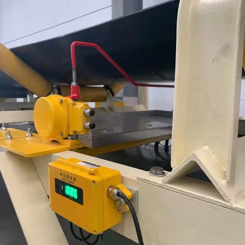
1. Cable-press type longitudinal tear detection device (high-sensitivity mechanical force sensing)
- Installation position: on the lower surface of the carrying run of the belt, 2 to 5 metres immediately behind the material loading point, between two sets of supporting idlers.
- Working mechanism: one or more fatigue-resistant stainless-steel detection wire ropes are tensioned transversely under the lower surface of the belt, with the rope ends connected to high-precision explosion-proof microswitches. When the lower end of a foreign object that has pierced the belt protrudes below the belt, the foreign object travelling with the belt directly presses down on or scrapes against the transverse wire rope.
- Actuation response: the instant the rope receives a small downward displacement (or a sudden tension change) it overcomes the internal spring resistance and drives the microswitch to output a hard-contact stop signal instantly, cutting off the main motor power supply within 0.1 seconds.
2. Concave-pan sliding and swinging type tear detection devices
- Concave-pan sliding detector: uses a curved pan that fully matches the bottom of the troughed conveyor belt, floating on sliding guides and return-torque springs. A penetrating foreign object contacts the pan surface, pushes it and produces displacement, which actuates the travel switch and trips the circuit; the sensing force area is large and the resistance to dust impact is strong;
- Swinging detector: a lightweight, wear-resistant flexible swinging baffle is suspended; a piercing foreign object or a falling torn belt strip pushes and rubs the baffle, producing an angular deflection, and when the swing angle reaches 15°–25° the contact closes and trips, with extremely light actuation resistance and high sensitivity.
3. Tear/spillage force-sensing detection pan
Making use of the fact that, when a penetrating tear occurs in the conveyor belt, the carried material will inevitably leak rapidly downwards through the slit, a spillage force-sensing pan and a gravity sensor are added below the idler frame in the rear part of the loading section. When local cracking causes continuous spillage accumulation, the change in gravitational torque on the pan triggers an alarm and shutdown, enabling accurate capture of small, slow tears in their early stage.
4. Machine vision and AI image-based online inspection of edge defects
In the clean return section of the conveyor belt, dust-proof and explosion-proof high-speed line-scan cameras and special laser structured light sources are installed, and edge-computing AI algorithms are used to scan and analyse the texture of the lower belt surface in real time. Millisecond-level quantitative identification of shallow scratches, local holes and torn fringes at the edges of the lower belt surface provides round-the-clock early health screening without mechanical contact.
V. Parameter and characteristic comparison matrix of the core technical units of the anti-tear system
The table below systematically reviews the technical parameters and applicability of the mainstream tear prevention and detection units used in industrial bulk material conveying:
| System unit category | Core working principle | Key technical performance and response time | Optimal engineering location | Typical working conditions and applicable media |
|---|---|---|---|---|
| Heavy-duty impact bed unit | Highly elastic rubber + UHMWPE sliding bars for continuous elastic support | Eliminates idler-gap jamming dead zones, absorbs 80% of vertical impact energy | The receiving section directly struck by material at the loading points of transfer chutes at each stage | High-drop receiving areas for metal ore, hard-rock mining and large raw coal |
| Foreign-object damping interception system | Heavy suspended damping chain curtain combing + strong iron removal and metal detection | Changes the falling posture of foreign objects so that they lie flat and slide, removing iron parts in advance | Inside the transfer chute channel and on the upstream feed conveyor | Large mine trunk lines prone to carrying mining anchor bolts, angle steel, picks and other mechanical scrap |
| Cable-press tear detector | A piercing foreign object presses down the transverse wire rope, and the sudden tension change triggers the microswitch | Purely mechanical force-sensing actuation, response time < 0.1 s, immune to dust interference | Below the carrying run of the belt within 2 to 5 metres behind the receiving point | Coal and ore conveying trunk lines with severe dust, high humidity and heat, and strong vibration |
| Concave-pan sliding detector | The troughed curved pan is pushed by a penetrating foreign object and slides along its guide rail, producing displacement | Large force-capturing area, effective identification of obliquely protruding piercing sharp objects at all angles | Between the first carrying idlers immediately behind the outlet of the loading impact bed | Large heavy-duty conveyors with frequent large lumps and wide belts (B ≥ 1200 mm) |
| Built-in loop self-checking belt | High-frequency closed induction loops are vulcanised into the belt; a broken loop stops the pulse | Non-contact electromagnetic detection, with positioning accuracy down to the loop spacing (50–100 m) | Multiple high-frequency excitation/receiving units along the line, covering long-distance monitoring of the whole line | Long-distance overland conveyors and long-distance underground main inclined shaft high-strength belt conveyors |
| Vision AI tear detection unit | High-speed industrial line-scan camera + laser structured light + deep-learning feature analysis | Real-time quantification of fine surface scratches, pores and delamination, with no mechanical wear | Clean, straight return section of the belt and the visible section at the drive pulley outlet | Automated pipe conveyors or trunk lines with high belt speed (≥ 3.15 m/s) and unattended operation |
VI. Standardised on-site engineering installation procedures and long-term closed-loop management criteria
To ensure that the entire tear prevention and detection system remains in a state of 100% sensitive actuation and zero false alarms all year round, on-site engineering implementation and operation and maintenance management must strictly follow the procedures below:
1. High-precision gap calibration of the detection rope and pan
- The physical gap between the wire rope of the cable-press tear detector and the lower surface of the unloaded conveyor belt must be precisely tuned, and under standard conditions it is usually maintained at between 20 mm and 30 mm. If the gap is too large, a small sharp object whose protruding length after piercing is insufficient cannot touch the sensor; if the gap is too small, the normal sag and vibration of the belt under heavy-load, high-throughput conditions will very easily cause frequent false shutdowns;
- The fit clearance between the impact bed and the skirt boards of the guide chute must be smooth and symmetrical, and an inverted wedge-shaped dead zone that is "wide at the front and narrow at the back" must be strictly avoided, so as to prevent crushed stone being squeezed in the corner between the skirt boards and causing man-made scratching.
2. Millisecond-level electrical hard-interlocked emergency braking circuit
The highly reliable normally-closed (NC) hard contacts output by the tear detection sensors must be connected directly in series into the high-voltage vacuum contactor of the main motor (or the safety emergency stop circuit ESTOP of the main frequency converter) by physical hard wiring; they must never be fed only as software signals into PLC polling.
- Contact actuation forcibly cuts off the main motor power supply within 0.1 seconds and simultaneously coordinates with heavy-duty mechanical hydraulic disc brakes for emergency mechanical braking;
- The control system interlocks at nanosecond level to stop the upstream feeding feeder and feed belt, completely eliminating system inertia coasting and keeping the tear length within the first few metres.
3. Long-term closed-loop management of "permit-based inspection + calibration and maintenance"
- Regular permit-based inspection system: for easily worn and easily detached components such as chute wear liners, cleaner blade fixing bolts and impact idler bearings, establish a mandatory regular permit-based inspection and torque-tightening ledger, so that hidden dangers of weld detachment and loosening are eliminated before they fall off;
- Weekly manual functional verification: taking advantage of the weekly routine shutdown maintenance window, the dedicated safety officer must manually press each cable-press linkage and push each concave-pan slider one by one, verifying on site whether the control room shutdown alarm signal and the high-voltage trip circuit are 100% sensitive in actuation, so as to completely prevent switch contacts from failing due to hardened damp coal sludge.
Through the combing of material at the source, flexible energy absorption by the heavy-duty impact bed at the loading point, and precise deployment of multi-dimensional force-sensing and optical detectors below, belt conveyors can build an intrinsic safety defence line with no blind spots, completely overcoming the enormously harmful industry problem of longitudinal tearing.