
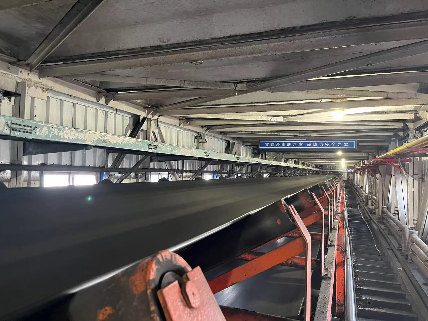
In the coal handling trestles of thermal power plants, underground mining faces and coal preparation plants of coal mines, coal transfer ports, as well as coking and metallurgical enterprises, belt conveyors are the key equipment that guarantees continuous, high-capacity transportation of bulk coal. However, coal handling environments are usually accompanied by high humidity, agglomeration of coal slime, airborne dust, and frequent impacts from lump coal and gangue, making the operating conditions extremely harsh. During continuous high-load operation, belt conveyors are highly prone to various electromechanical and structural failures.
Statistical data shows that among all equipment shutdown events on coal handling lines, belt deviation has consistently ranked first in frequency, followed by drive slip, longitudinal tearing and belt breakage, spillage along the line, drive unit failures, and stall "runaway" under steep downhill operating conditions. The reason deviation becomes the focus of the entire line is that it is not only an independent motion imbalance fault, but also the "upstream culprit" that induces material leakage and spillage, belt edge tearing, idler damage, and even severe belt breakage accidents. When the belt deviates severely, its edge rubs violently and is squeezed against the fixed frame, and the tensile stress on one side rapidly exceeds the lateral and longitudinal load limits, which very easily triggers catastrophic tearing or belt breakage in an instant.
To improve the safe operating level of coal handling systems and reduce unplanned downtime losses, equipment management and front-line technical personnel must look beyond surface phenomena and, starting from mechanical principles and operating environments, systematically master the root causes of common failures and the corresponding scientifically grounded countermeasures.
I. Belt Deviation: The Most Frequent Core Failure That Most Easily Leads to Misjudgment
When dealing with deviation on site, the habitual action of many maintenance personnel is to blindly install additional self-aligning idlers (self-training rollers) or to replace them over large areas. However, field engineering experience shows that the root cause of many deviations is not the centering performance of the idlers at all. If self-aligning idlers are installed blindly while basic installation errors or off-center material loading have not been eliminated, the deviation cannot be thoroughly corrected; on the contrary, the belt will develop periodic wavy lateral jumping and swaying as it travels, which aggravates wear and creates new problems.
1. Two-Dimensional Precise Localization of Deviation Root Causes
When troubleshooting deviation, it is recommended to cross-check along two dimensions: "where it occurs" and "how it behaves":
| Classification dimension | Specific symptom | Typical root causes and investigation direction |
|---|---|---|
| By position along the line | Deviation on the carrying run (upper idler area) | Off-center material loading at the transfer chute discharge point, frame levelness out of tolerance, belt splice (vulcanized or mechanical) not perpendicular |
| By position along the line | Deviation on the return run (lower idler area) | Failure of head and return-run cleaners, heavy wet-coal encrustation bonded to the lower idlers or bend pulley surface |
| By position along the line | Localized deviation (always at one specific section) | Seized and worn-flat idler bearings in that area, severely skewed idler brackets, idler dropout, or local frame settlement |
| By operating pattern | Fixed-position deviation (regardless of how the belt surface cycles) | Basic installation error, idler axis at that point not perpendicular to the belt centerline, local mechanical deformation of the frame |
| By operating pattern | Wandering deviation that follows the belt revolution cycle | Uneven mass distribution of the belt itself, excessive serpentine camber of the belt, splice cut not square but at a diagonal angle |
2. Mechanical Correction Rules for Installation and Geometric Errors
The installation accuracy of the conveyor frame directly determines the running attitude of the belt. Non-parallel axes of the head drive pulley and the tail bend pulley, centerlines of the frame not coinciding along the whole line, or differences in the surface friction coefficient of the idlers after long-term heavy-load scouring and uneven shaft diameter wear will all cause an imbalance of traction resistance on the two sides of the belt.
When adjusting deviation caused by installation errors of the pulley bearing housings, the correction principle of "adjust the side toward which the belt deviates" must be strictly followed:
- If the belt shifts toward bearing housing A at the head pulley, the A-side bearing housing should be moved slightly in the direction of belt travel, or the opposite B-side bearing housing should be moved slightly in the reverse direction, so that the pulley axis applies a corrective squeezing force to the belt;
- For localized deviation caused by skewed idlers, follow the rule of "adjust the rear, not the front": slightly shim up the idlers located behind the deviating side, in the direction of belt travel.
3. Chained Destructive Effects of Deviation
The chain damage caused by deviation must be guarded against: mild deviation causes raw coal to spill over the skirt board, resulting in severe coal and dust accumulation along the gallery, sharply increasing manual cleaning workload and the risk of dust explosion; with severe deviation, the edge of the high-speed belt presses hard against the angle-steel frame and rubs violently, causing the edge rubber to wear away rapidly and exposing the inner nylon/polyester canvas layers or steel cord core to corrosion. With tensile strength sharply reduced, once impacted by large lumps of coal or gangue, the edge and the belt are easily torn, resulting in total line paralysis and production shutdown. In addition, the lateral off-center force generated by deviation is transmitted to the pulley and idler shaft ends, inducing pulley shaft displacement and early fatigue bursting of idler bearings.
II. Drive Slip: Mechanical Evolution of Insufficient Friction Torque and Coal Slime Encrustation
A conveyor transmits power through the friction between the drive pulley and the belt. According to the classic Euler friction traction theory, the maximum circumferential force transmitted by the pulley depends on the pre-tension of the belt at the point of contact with the pulley, the wrap angle, and the static friction coefficient between the two.
1. Common Causes of Slip
The core causes of slip on coal handling lines concentrate on three points:
- Severely insufficient belt pre-tension: the take-up device reaches the end of its travel, the counterweight falls off, or the hydraulic tensioning system leaks pressure, causing the belt to become slack;
- Worn pulley lagging and a sharp drop in friction coefficient: the diamond or herringbone lagging pattern on the pulley surface is worn flat, or a smooth bare metal drum surface with a lower friction coefficient has been selected;
- Ingress of moisture and sticky coal slime: when the raw coal conveyed has a high moisture content and a large slime fraction, fine coal powder easily penetrates together with moisture onto the non-working (inner) surface of the belt.
2. The Vicious Damage Cycle of Coal "Build-Up"
Under wet and sticky conditions, if the cleaning system is not thorough, the coal slime on the inner surface is repeatedly crushed and compacted by the enormous tensile force as it passes over the drive pulley and the snub pulley, rapidly bonding into hard, dense raised lumps on the pulley surface (commonly known as pulley "build-up"). Such localized build-up makes the pulley circumferential surface uneven: on one hand, it causes abnormally severe alternating concentrated bending tensile stress in the belt, leading to delamination between the carcass and the top and bottom cover rubber; on the other hand, it unbalances the equivalent outer diameters on both sides of the pulley, inducing severe dynamic slip and violent deviation.
Therefore, on coal handling lines, an efficient cleaning system is not only an indicator of good housekeeping, but also the fundamental precondition for ensuring friction drive, preventing pulley encrustation and build-up, and eliminating slip accidents.
III. Tearing and Belt Breakage: The Most Serious Mechanical Failures
Among all belt conveyor failures, longitudinal tearing and transverse belt breakage cause the most severe direct asset losses and the longest production downtime.
1. Key Sources of Tearing
The physical sources of longitudinal tearing are highly concentrated in the material discharge point area:
- Puncture and jamming by foreign objects: large, high-hardness debris mixed in during coal mining and washing (such as broken crusher hammer plates, alloy picks from shearers, steel beam joints, mine support anchor bolts and wire mesh) falls from the transfer chute several meters high with extremely high kinetic energy. Once a sharp object pierces the belt carcass and is firmly jammed by the idler crossbeam or the skirt board column below, the rapidly moving belt slides forcibly relative to the jammed blade, and the entire belt is split longitudinally within seconds;
- Detachment and damage of equipment components: loose and fallen bolts of the wear-resistant liner inside the transfer chute, cracking and collapsing metal material baffles, or breakage of the cleaner mounting frame directly become sharp "man-made blades";
- Severe material stagnation and crushing: material blockage inside the chute spreads to the pulley position, and the accumulated lump coal bursts under pulley crushing and punctures the belt body.
2. Main Causes of Belt Breakage
Transverse full-section belt breakage is usually closely related to the following electromechanical factors:
- Long-term overload operation causes the transient tensile stress borne by the belt to exceed the mechanical strength safety factor;
- Poor belt splicing workmanship, fatigue cracking of mechanical fasteners, or aging, debonding and delamination of the rubber inside cold/hot vulcanized splices, with the strength reduction at the splice reaching the critical point;
- Poor soft-start characteristics of the drive unit, generating a huge dynamic tension shock wave (a water-hammer-like tension wave) at the instant of starting;
- Deviation wear damaging the edges and breaking wires, so that the remaining effective cross-section cannot withstand the full load tension.
3. Dual Defense Lines: Prevention and Condition Monitoring
Preventing tearing and belt breakage must adhere to the comprehensive principle of "structural prevention first, intelligent monitoring as a supplement":
- Material path optimization: install heavy-duty screening grids and damping curtains above the discharge chute, and deploy upstream high-suction suspended electromagnetic iron removers and all-metal detectors to screen out sharp, long, large iron objects;
- Flexible modification of the discharge point: fully replace traditional rubber impact idlers with continuously supported, high-damping heavy-duty impact beds at the transfer receiving section. The flat, continuous ultra-high-molecular-weight polyethylene slide bars of the impact bed completely eliminate the suspended gaps between idlers, so sharp objects falling with the material cannot form a jamming fulcrum, thus eliminating the conditions for puncture and jamming at the source;
- Multi-dimensional online monitoring and warning: densely install pressure-rope type tear sensors, under-receiving leak-sensing trays and machine vision inspection units behind the discharge point. Once perforation leakage or rope displacement is detected, power is tripped and the machine is stopped within milliseconds, limiting tear losses to the minimum range.
IV. Typical Drive Unit Failures: Motor, Reducer and Coupling Troubleshooting
The drive assembly is the heart of a belt conveyor, including the electric motor, reducer, hydraulic coupling and drive pulley set. In heavy-load and dusty environments, its common failure manifestations and countermeasures are as follows:
1. Motor Failures and Abnormal Overheating
- Motor fails to start: first check whether the voltage drop of the upstream power supply line is too large, and whether the vacuum contactors and relays of the control circuit refuse to operate; for wound-rotor motors or variable-frequency motors, check the starting resistor cut-out sequence or the inverter trip parameters;
- Severe motor heating and overtemperature: if the motor surface temperature rise is abnormal, it is mostly due to overload of the conveying cross-section on long-distance conveyors, or local material accumulation and jamming in the chute causing a sharp increase in running resistance along the whole line. At this time, a power meter or current transformer must be used to measure the three-phase running current, and the load must be verified against the conveying capacity; it is strictly forbidden to blindly increase the thermal relay protection setting to force operation.
2. Reducer Overheating, Abnormal Noise and Vibration
- Overheating of the housing: mainly caused by abnormal lubricating oil quantity (oil level too high causing gear oil-churning heating, or too low causing dry friction), deterioration of lubricating oil quality, mismatched viscosity, and damage to internal bearing clearances. Oil purity should be tested regularly, and oil should be replenished and changed in precise quantities according to the oil sight glass scale;
- Gear abnormal noise and tooth surface pitting: heavy-load starting impacts and insufficient frame rigidity easily cause offset load wear, pitting spalling or tooth breakage on gear tooth surfaces. A vibration spectrum analyzer should be used to regularly measure the vibration severity at the input and output bearing housings, and the coaxiality between the motor and reducer axes should be corrected in time.
3. Transmission Failure of Hydraulic Couplings and Couplings
- Unable to transmit rated torque at full load: the working fluid in the working chamber (special anti-wear hydraulic oil or water medium) is insufficient. Fluid must be filled strictly within the factory filling rate range, and overfilling or underfilling is strictly prohibited;
- Frequent melting and spraying of fusible plugs: fluid spraying from the coupling is an overheating protection action indicating severe overload of the conveyor, prolonged stalling and slipping, or frequent starting. After spraying occurs, the root cause of jamming or overload on the conveying line must be fully identified, and it is strictly forbidden to arbitrarily replace standard fusible plugs with ordinary solid plugs;
- Load imbalance in dual-motor or multi-motor drives: when two motors drive the same pulley or the front and rear pulleys, if the coupling filling volume or the motor mechanical characteristics differ slightly, one motor will be overloaded and hot while the other is underloaded. During operation, the real-time currents of the two motors must be monitored, and the coupling filling volume fine-tuned to achieve torque balance.
V. An Easily Overlooked Hazard: "Runaway" Loss of Speed on Downhill Belt Conveyors
On coal handling lines with a large inclination that convey downward (such as downhill gate roads in mining areas and downhill trestles on mountainsides), there is a special operating condition with enormous destructive power — the downhill "runaway".
1. Dynamics of Runaway Occurrence
When material is conveyed downward, the downhill gravity component of the material and the belt itself acts in the same direction as the running direction. When the downhill force is greater than the running resistance, the material does work on the drive system, and at this moment the motor operates in a regenerative braking state.
If multiple upstream coal feeders feed material simultaneously in a disordered manner, causing the instantaneous downhill load to seriously exceed the rated carrying capacity, the gravity-driven dragging torque will quickly exceed the maximum allowable braking torque of the motor. At this point, the electrical system trips and releases on overcurrent, and if the mechanical brake has insufficient braking torque or a slow response, the belt will accelerate out of control in the reverse or forward direction under the action of gravitational acceleration like an unbridled horse, forming a "runaway".
2. Devastating Consequences and Technical Defense Against Runaway Accidents
Once runaway occurs, the enormous centrifugal force and dynamic tension generated by overspeed operation will destroy the mechanical system within seconds: the belt breaks and flies apart, the reducer gears shatter, the motor overspeeds and burns out, the hydraulic disc brake cracks and fails at high temperature, hundreds of idlers fly off and fall, and a large amount of raw coal pours out and floods the entire roadway.
To prevent downhill runaway, reliable hardware braking protection must be built:
- It is strictly forbidden to arbitrarily increase the feeding frequency of the coal feeders, and any overloaded downhill operation must be eliminated;
- A highly reliable electro-hydraulic proportional controllable soft braking system or heavy-duty hydraulic normally-closed disc brake must be provided, to ensure that the brake can decelerate and lock according to a smooth deceleration rate when the power supply fails and the machine stops;
- Independent centrifugal overspeed detectors and overspeed and stall switches must be installed along the line; once the belt speed exceeds 110% to 115% of the rated speed, the safety hard circuit shall be triggered instantly to implement mechanical emergency braking.
VI. Long-Term Management Regulations for On-Site Electromechanical Operation and Maintenance, and a Quick Troubleshooting Mnemonic
To improve the availability of coal handling line equipment and reduce sudden accidents, the on-site electromechanical team should solidify troubleshooting experience into standardized inspection checklists:
1. The Golden Troubleshooting Mnemonic
- First look at where and how the belt deviates, then check pre-tension and sticky coal;
- For tearing, strictly inspect discharge points and scrap iron; for drive faults, measure oil, electricity and shafts;
- For downhill lines, the key is braking and overspeed prevention; with cleaning in place, everything is settled.
2. Daily Crew Inspection and Long-Term Maintenance Guidelines
- Pre-shift static inspection: check the centerline alignment marks at the head and tail, verify the tightening status of idler bracket bolts, and remove local hard coal-slime lumps on the surface of the drive pulley and return idlers;
- Dynamic observation under heavy load: when the conveyor runs at full load, patrol along the line to observe the swing amplitude of the belt on the carrying and return runs; observe whether the material inside the discharge chute is in a centered flow state, and eliminate unilateral off-center loading;
- Full-cycle assurance of the cleaning system: check daily the contact degree and wear allowance of the primary polyurethane scraper and the secondary alloy blade at the head, so as to ensure that the lower surface of the return belt is clean and dry without floating coal adhesion;
- Action verification of safety protection devices: every month, strictly perform on-site manual toggle and pull tests on the two-stage deviation switches, bi-directional pull cord switches, slip detectors and tear-sensing devices along the line, ensuring that the alarm and trip signals fed back to the central control room are 100% sensitive and reliable.
By systematically mastering the geometric mechanism of deviation, the frictional mechanical balance of slip, the front-end energy dissipation of tearing, and the strict control of downhill braking conditions, enterprises can thoroughly turn "post-event firefighting" into "pre-event prevention", and comprehensively build a solid electromechanical intrinsic safety defense line for bulk material coal conveying lines.