
Chapter 1: Blockage Risks at Bulk Material Transfer Stations and the Need for Anti-Blocking Protection
In continuous-process industries such as mining and ore dressing, coal handling systems of thermal power plants, bulk cargo terminals at ports, metallurgy, and cement and building materials production, belt conveyors and discharge chutes form the core pipeline for transferring materials between pieces of equipment. During daily high-load operation, increased material moisture, higher stickiness, jammed foreign objects or a sudden surge in feed rate can easily cause material accumulation and blockage inside the discharge chute.
Once a chute is blocked, if no anti-blocking detection device responds in time, the following material will quickly fill the chute and press against the upstream conveyor belt, very likely causing serious accidents such as belt slippage and wear, longitudinal tearing, motor overload and burnout of the belt conveyor, and a large amount of material spilling and spreading. This not only results in huge production shutdown losses and equipment repair costs, but may also create safety hazards for on-site inspection personnel.
To achieve automated interlock protection and safe production of the conveying system, real-time monitoring of the material accumulation state on the side wall of the transfer chute is essential. As a mechanical pressure-actuated (movable gate type) high-reliability industrial sensor, the XLDS-I Chute Jam Detector can accurately sense pressure and output a switching signal in the early stage of material blockage and accumulation, becoming the "safety gate" that guarantees smooth operation of the entire bulk material transfer process.
Chapter 2: Working Principle and Structural Features of the XLDS-I Chute Jam Detector
2.1 Movable Gate Pressure Actuation and Switching Signal Response Mechanism
The XLDS-I chute jam detector adopts the sensing mechanism of a mechanical movable gate deflected by pressure, and is installed on a chute side wall position that is not subject to direct impact from normally falling material.
- Normal material flow state: The material flows and falls smoothly inside the chute, so the lateral pressure on the chute side wall and the detector movable gate is extremely small. The detector movable gate keeps its vertical closed initial state and the internal switch remains in its normal state.
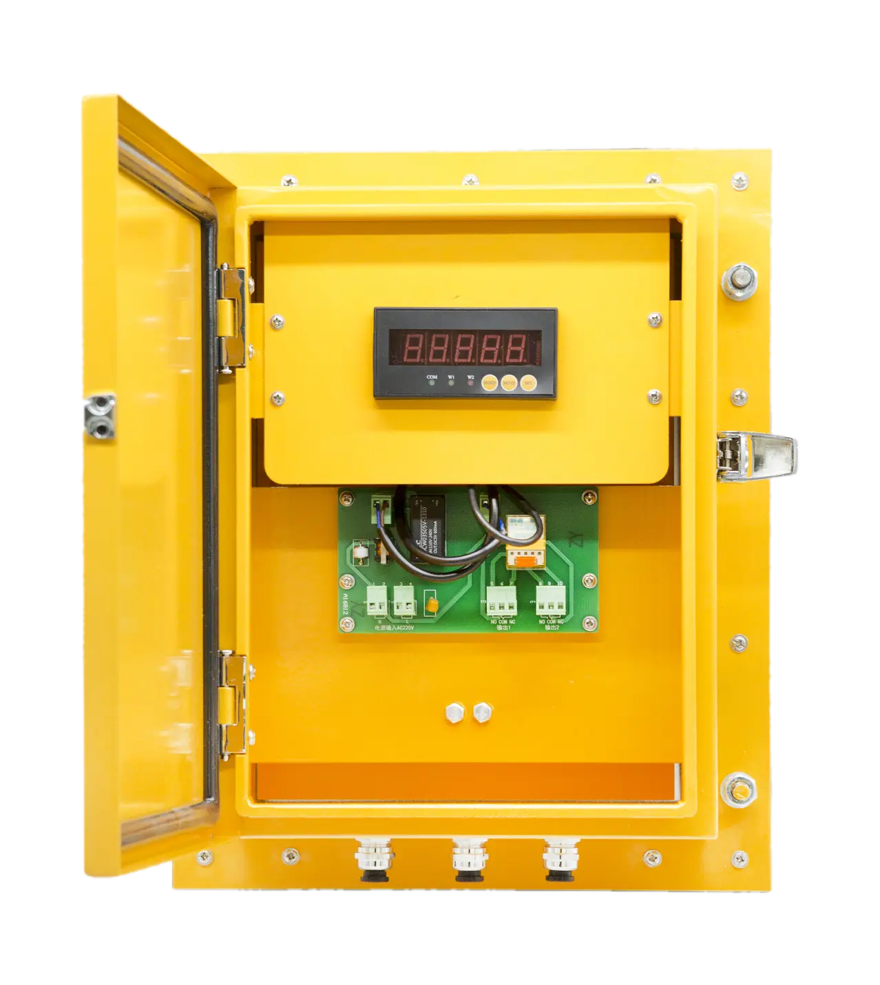
- Blockage and accumulation state: When a blockage occurs at the chute outlet or inside it, the height of the accumulated material rises rapidly and forms a continuously increasing lateral squeezing pressure on the chute side wall. The accumulated material pushes the detector movable gate outward. When the gate control switch is actuated, the internal contacts flip instantly and promptly output independent normally open (NO) and normally closed (NC) switching signals. These signals can be connected directly to a PLC/DCS control system to realize interlock alarms or to control emergency shutdown of upstream equipment.
- Automatic rapping and reset mechanism: If the switching signal is connected to the control circuit of an on-site blockage-clearing rapper, the rapper can be started automatically without stopping the line to clear light chute blockages. After the blockage is cleared and the material drops down, the movable gate automatically resets under the gravity of the mechanism and is ready for the next monitoring cycle.
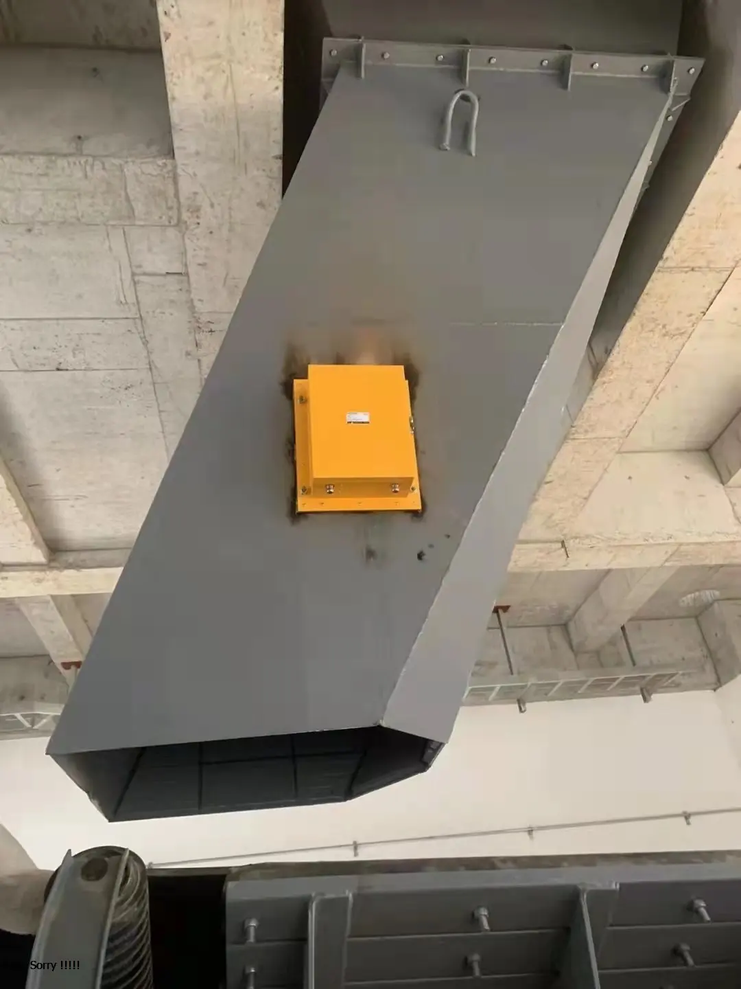
2.2 Reinforced Anti-Corrosion and Dust-Proof Protection Design
- High-temperature powder-coated anti-corrosion enclosure: The surface of the detector housing is treated with a professional powder coating process, providing extremely strong acid and alkali resistance and corrosion resistance, effectively coping with humid and sulfur-containing working environments.
- Highly sealed dust-proof structure: The protection rating reaches IP54. The enclosure joint surfaces are fitted with sealing gaskets and elastic rubber plates, which can effectively block the intrusion of high-concentration industrial dust and water vapor on site and protect the internal electrical contacts.
Chapter 3: XLDS-I Core Technical Parameters and Performance Specifications
To help engineers and procurement teams select equipment accurately, the table below lists the official technical parameter specifications of the XLDS-I chute jam detector:
| Technical Parameter | Official Specification / Performance Description |
|---|---|
| Product Model | XLDS-I Chute Jam Detector |
| Output Type and Quantity | 2 × SPDT (two sets of single-pole double-throw dry contacts, independent NO/NC outputs) |
| Contact Rating | AC 380V 3A / DC 24V 3A |
| Reset Mode | Automatic Reset |
| Protection Rating | IP54 (dust-proof and splash-proof design) |
| Ambient Temperature | -20°C to +50°C |
| Relative Humidity | 0% – 95% RH |
| Atmospheric Pressure | 80 kPa – 110 kPa |
| Applicable Cable Diameter | Ø 6 mm – 10 mm |
| Overall Dimensions | 410 mm × 330 mm × 142 mm (mounting cut-out: 260 mm × 260 mm) |
Chapter 4: Installation Steps and Anti-False-Trip Baffle Rules
To ensure that the XLDS-I chute jam detector operates stably under harsh working conditions without false tripping, the following installation rules must be strictly followed:
4.1 Installation Position and Height Recommendations
- Installation position: Select one of the chute side walls on either side of the belt, avoiding the main parabolic impact path of the falling material.
- Recommended installation height: It is generally recommended to install the detector at about 2/3 of the height from the bottom of the chute.
- Dual-unit installation scheme: If both "early alarm" and "emergency shutdown" functions are required at the same time, two detectors can be installed as a combined upper and lower group — the alarm unit is recommended at 1/3 of the height from the bottom, and the shutdown unit at 2/3 of the height.
4.2 Construction and Welding Steps
- Cutting the chute side wall opening: First cut a square mounting opening of 260 mm × 260 mm at the selected position on the chute side wall.
- Welding the impact protection baffle (critical step): Weld an inclined baffle of about 300 mm × 150 mm on the inner wall of the chute at 100 mm – 200 mm above the opening. This baffle can effectively shield the detector movable gate from being directly struck by large pieces of material falling from a great height, eliminating false tripping caused by material impact.
- Welding and fixing the backing plate: Weld the matching mounting backing plate at the opening in the chute side wall (note that the wide side faces upward), and then fasten the XLDS-I chute jam detector body to the backing plate with bolts.
Chapter 5: Wiring Instructions and Routine Maintenance Rules
5.1 Safety Precautions and Wiring
- Live-line work is strictly prohibited: The power supply must be cut off before installation, wiring or maintenance to prevent electric shock accidents.
- Explosion-proof limitation: This product is of non-explosion-proof design and must not be used in environments with flammable and explosive gases or highly explosive dust.
- Wiring rules: Use a sheathed cable with a nominal diameter within the range of Ø6 – 10 mm to pass through the cable gland, connect the cable to the internal microswitch contacts according to the wiring schematic diagram, and fully tighten the sealing nut.
5.2 Routine Maintenance and Troubleshooting
- Regular dust removal and switch inspection: Regularly remove the dust accumulated around the detector movable gate and on the surface of the terminal box, and manually push the movable gate to verify whether the microswitch output signal is normal.
- Check the elastic rubber plate: Frequently check whether the elastic rubber plate at the sealing position between the movable gate shaft and the enclosure is aged, torn or hardened. If damaged, it should be replaced in time to prevent dust or water vapor from penetrating into the enclosure and damaging the electrical components.