
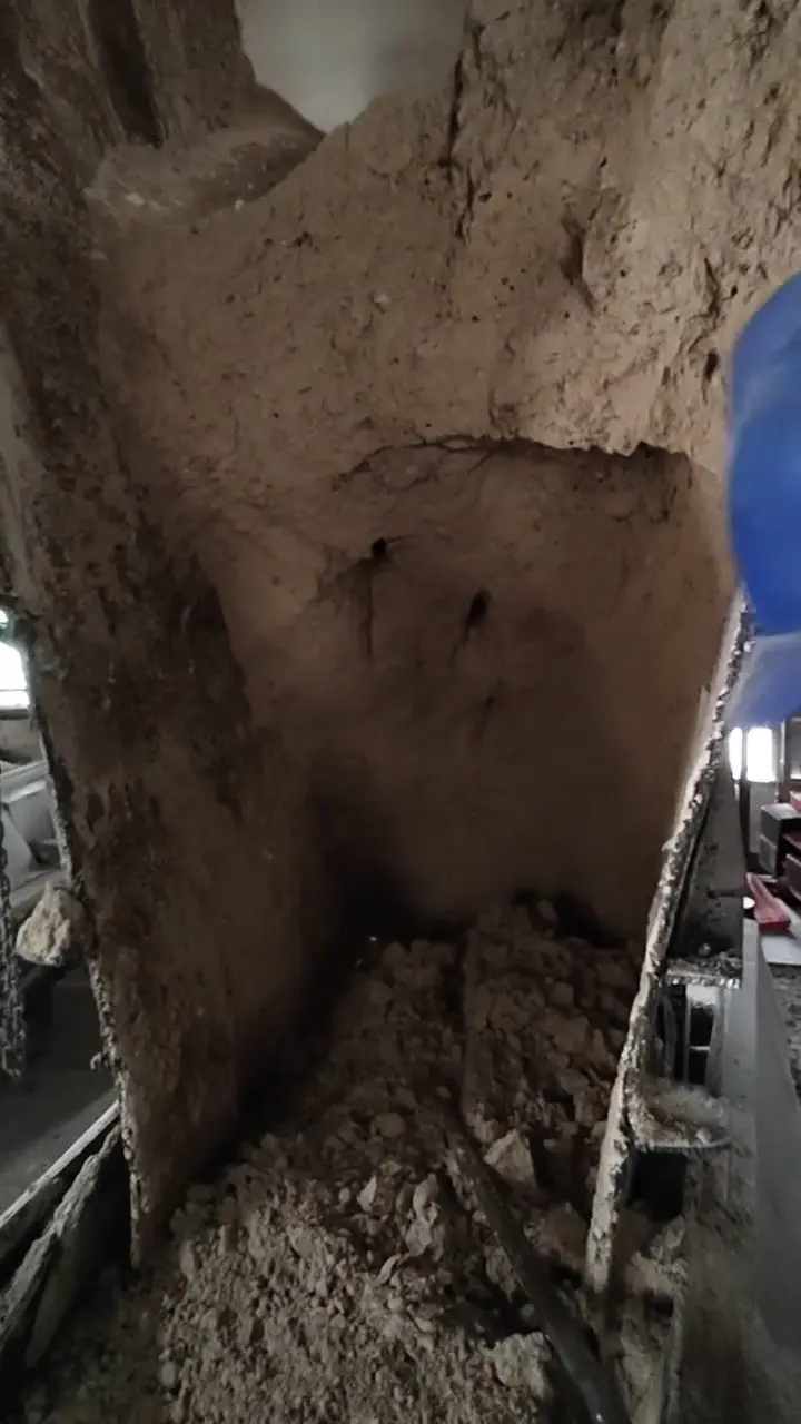
On modern new dry-process cement clinker and cement grinding production lines, the raw material batching station and the mixed-material blending system are the critical throat that determines both the qualification rate of the raw meal and the continuous, stable calcination of the rotary kiln. In this process, limestone, sandstone (siliceous corrective material), iron slag or pyrite cinder (iron corrective material), desulfurized gypsum and various types of slag must be supplied continuously and precisely through large raw material storage silos and batching weigh-feeder systems.
In day-to-day production operations, however, the frequent blockage of sandstone silos, iron slag silos, wet limestone silos and clayey raw material silos has for many years been a major chronic problem for cement producers. Especially when the rainy season drives a sharp rise in the moisture content of the material, when the fine-powder fraction is excessively high and when clayey impurities are abundant, the material readily forms stubborn arches at the contracting section of the silo's lower cone and at the discharge outlet, builds up and cakes severely on the silo walls, and may even stop flowing altogether.
Once a silo is blocked, the batching scale is instantly starved of material, which directly destroys the raw meal proportioning balance (the three modulus values are severely disturbed) and forces the raw mill to reduce output or even stop; if the discharge from a main raw material silo is interrupted, it frequently causes insufficient feed at the kiln inlet, disorder of the process thermal regime and even unplanned kiln shutdown and feed cut-off, resulting in direct production losses of hundreds of thousands to more than a million yuan. More seriously, traditional manual handling of silo blockage usually requires operators to carry iron rods and pneumatic picks and to crawl into the narrow, dim, dust-laden interior of the silo or to poke and dig material upward from the discharge outlet. This way of working is not only extremely labor-intensive and time-consuming, but is at every moment exposed to the enormous safety risks of falling from height, sudden large-scale material collapse and burial, and oxygen deficiency leading to asphyxiation.
To guarantee the intrinsic safety and process stability of continuous cement production and to overcome the silo blockage problem once and for all, the cement industry has gone through a profound technological evolution — from adding air cannons, laying wear-resistant liners and installing external silo-wall vibrators to a new generation of suspended liner vibration arch-breaking technology and intelligent multi-dimensional closed-loop anti-blockage systems.
I. Material Characteristics and Arch-Formation Dynamics of Sandstone, Iron Slag and Limestone Silos in Cement Plants
The gravity flow of bulk solids inside the contracting cone of a silo follows the combined laws of non-Newtonian fluid mechanics and solid mechanics. The reason why the key corrective-material silos of a cement plant are so prone to stagnant material and blockage is jointly determined by their specific physicochemical properties and their mechanical state:
1. High moisture and wet-stickiness of sandstone, iron slag and similar raw materials
- High moisture content and surface capillary attraction: sandstone stored in the open readily absorbs water, and iron slag (especially wet granulated slag or pyrite cinder produced as a by-product of steel plants) typically has an initial moisture content as high as 8%~15% or more. Fine particles mixed with water form a dense free-water film, and the particle interfaces generate powerful capillary water-bridge adsorption forces and van der Waals attraction, causing the fine powder to aggregate rapidly from a loose state into highly cohesive mud lumps.
- High abrasiveness and plastic extrusion hardening: sandstone is rich in silicon dioxide () and is hard with sharp, angular edges; iron slag has a high specific gravity and high density. When the material falls from a silo top dozens of metres high, the enormous potential energy of its own weight is converted into static pressure, generating extremely high normal compressive stress in the contracting section of the cone and forcing the wet, sticky powder to compact and harden at the converging funnel.
2. Four typical flow-retarding forms inside the silo
Under the constraints of gravity and the converging cross-section boundary, four typical mechanical forms of blockage usually develop inside a silo:
- Mechanical arching: when large lumps of limestone or coarse-crushed sandstone converge at a narrow discharge outlet, the particles interlock with one another because of their irregular geometry, forming a "hinged equilibrium stone arch" strong enough to support the dead weight of the entire silo contents above it;
- Cohesive arching: for fine wet mineral powder and iron slag mud, because the cohesive shear strength between powder particles is greater than the downhill component of the material's gravity, a thick "soil-like self-supporting arch" spontaneously bridges across the span above the throat of the discharge outlet, leaving a void below and cutting off the flow;
- Ratholing: when the external friction angle between the material and the silo wall is greater than the wall inclination angle, the material clinging to the wall cakes and solidifies completely and stays motionless, and only the material in the central vertical channel can trickle down, forming a deep well-like circular hole. Ratholing not only reduces the effective live capacity of the silo by more than 70%, but the consolidated material on the periphery is also very likely to collapse suddenly when humidity changes, smashing the quantitative feeder scale below;
- Wall build-up and caking: with long-term static contact between the material and the steel silo wall, physicochemical adsorption with the metal surface occurs under the oxidizing action of humid air, and the crust grows layer by layer from a few centimetres to tens of centimetres, completely altering the effective discharge converging cone angle for which the silo was originally designed.
II. In-Depth Reflection on the Engineering Limits and Fatal Drawbacks of Conventional Anti-Blockage and Blockage-Removal Methods
For many years cement plants have tried a variety of conventional means to solve the arching and wall build-up problems of the above materials, yet all of them have exposed insurmountable engineering shortcomings in long-term operation:
1. Air cannon pulse cleaning: rapid energy attenuation and insufficient dead-zone penetration
Air cannons clear material by means of the shock wave generated when high-pressure air is released instantaneously from an air receiver. However:
- the energy of the shock wave attenuates exponentially and rapidly in a loose, porous powder pile, and the effective action radius is usually less than 0.8 to 1.2 metres;
- the high-pressure air stream usually only penetrates along the pores of least resistance in the material, punching a hole through it (forming an "air-channel perforation"), and after the air has passed, the heavy, wet, sticky material caked around it still does not move at all;
- if the material is extremely wet and viscous, the high-pressure jet of compressed air may even push and compact local wet slime or iron slag further, forming an even denser hard crust.
2. Static wear-resistant anti-stick liner: effective at first but prone to detachment and jamming
Lining the inner wall of the cone with ultra-high molecular weight polyethylene (UHMWPE) or microcrystalline ceramic plates is intended to reduce the interfacial friction coefficient. But under the long-term impact of large, hard sandstone lumps falling from a great height, plastic liners readily warp and deform; once the fixing bolts fracture under vibrational shear, the detached large liner plates slide into the discharge outlet and directly cause mechanical jamming and shutdown of the rotary valve or weigh-feeder below.
3. Fatal drawbacks of conventional external wall vibrators (bin vibrators)
In order to destroy the cohesion of the material directly, a large number of cement plants have shifted their focus to externally mounted silo-wall vibrators. Their principle is to apply periodic high-frequency, high-force impacts to the rigid outer wall of the silo through the high-speed eccentric rotation of a vibration motor. On industrial sites, however, this conventional technology exposes three fatal drawbacks:
- Fatigue damage of the silo wall and cracking of welds: conventional vibrator motors are usually welded or hard-bolted to the outer steel plate of the silo. Because the silo body itself is a super-heavy rigid structure of several tonnes or even tens of tonnes, the high-frequency alternating stress acts directly and continuously on the silo wall plate, causing the base metal around the motor mounting base to develop alternating fatigue tearing rapidly, and in severe cases causing large-area tearing of the welds of the silo cone and dust leakage, greatly shortening the overall design life of the silo;
- Small effective radiation area of the vibration energy and absorption by the structure itself: a large silo has extremely high stiffness, so the vast majority of the vibration force of an external motor is absorbed and dissipated by the huge, heavy steel wall itself; the effective shear acceleration actually transmitted to the material interface attenuates severely, and the effective radiation range is often limited to a local circumference of less than half a metre around the motor base;
- Secondary densification of the material caused by blind vibration (the vibratory-compaction effect): when the silo outlet has already arched and blocked while the vibrator keeps vibrating, the high-frequency wave transmitted by the outer wall not only fails to make the material fall, but acts like a concrete poker vibrator, violently compacting the fine sandstone and iron slag inside the silo that are already at their plastic limit, so that the cohesive force soars several-fold and the already blocked material becomes a "hardened dead block" as solid as rock.
III. Technology Upgrade Path: Structural Breakthrough of Suspended Liner Vibration Flow Assistance
In order to fundamentally eliminate the twin contradictions of "the silo wall being cracked by vibration" and "insufficient vibration energy", bulk-solids flow engineering specialists, on the basis of extensive field tests and elastoplastic mechanics calculations, have made a breakthrough reconstruction of the conventional vibration architecture — suspended flexible liner vibration flow-assistance technology.
1. Fundamental change in structure and working mechanism
This solution completely changes the crude mode of "violently shaking the rigid silo wall from the outside in", and its core design concept lies in "separation of static and dynamic parts, direct access to the interface":
- Physical isolation of the liner system from the rigid silo body: inside the contracting cone of the silo where blockage easily occurs, a layer of specially shaped arc or polygonal high-strength elastic wear-resistant alloy liner is installed independently in suspension. Between the back of the liner and the rigid silo wall, special high-damping, ageing-resistant rubber damping pads or flexible damping suspension members are fitted, so that the liner and the external main silo body are completely decoupled from each other in structural mechanics;
- The vibration source drives the liner directly: the force-transmitting shaft of the vibrator motor passes through a sealed flexible sleeve hole in the silo wall, and its excitation output end is rigidly connected directly to the back of the internally suspended liner.
2. Core technical advantages and mechanical comparison
- Complete elimination of silo body fatigue cracking and a substantial extension of silo service life: the high-frequency alternating exciting force is 100% confined to the lightweight liner structure, while the huge external load-bearing silo wall stays in a fully protected, static stress state. The high-damping damping members cut off the transmission path of the vibration force to the silo wall, and motor base tearing and weld cracking are completely eliminated;
- Geometric expansion of the effective vibration radiation area: because the liner is light in weight and reasonably matched in stiffness and flexibility, the excitation energy released by the vibration motor is not dissipated by the tens-of-tonnes heavy silo body, but instead makes the entire liner resonate uniformly at small amplitude and high frequency with extremely high transmission efficiency. The effective vibration radiation area is more than 3 to 5 times larger than that of the conventional external wall pad arrangement;
- Interfacial micro-shear arch breaking that completely disintegrates material agglomerates: the vibrating liner moves in periodic micro-displacement relative to the outermost layer of material. On the one hand, this alternating motion destroys the physically adsorbed water bridges formed by water capillaries, causing the external friction coefficient between the material and the liner to drop sharply; on the other hand, it applies high-frequency shear acceleration to the material layer close to the wall, keeping the particles inside the material in a loose, fluidised, unstable state, fundamentally overcoming the internal friction and cohesion of the material and enabling it to slide down smoothly under its own weight.
Intelligent Anti-Clogging and Material Flow Assisting System
IV. Multi-Dimensional Perception and Closed-Loop Control of the Intelligent Anti-Clogging and Material Flow Assisting System
If mechanical devices alone lack accurate perception, excessive and blind vibration when the discharge has completely stopped can still trigger "secondary vibratory compaction". Modern industrial silo management must build an intelligent closed-loop system that integrates "multi-dimensional online condition monitoring (Unit A)" with "adaptive stepped blockage-clearing execution (Unit B)".
1. Four-dimensional state perception of the blockage detection unit (Unit A)
The system deploys four types of online detection sensors around the clock at the critical blockage-prone nodes of the silo, so as to capture the precursors of flow stoppage at an early stage:
- Microwave non-contact blockage detection unit: based on the mechanism of microwave transmission attenuation, it is arranged in a through-beam configuration on both sides of the contracting discharge outlet of the silo. When the material falls discretely, the signal penetrates normally; once bridging or arching occurs inside or high-density stagnant material accumulates, the microwave beam is instantaneously interrupted and an over-limit alarm signal is output within 0.5 seconds, which also prevents large sandstone lumps from damaging the probe;
- Tilting-pressure (movable flap) level detection unit: installed on the side wall of the silo discharge pipe and the transfer chute that does not face the direct impact. Once material congestion spreads, the lateral squeezing force pushes the pressure-bearing flap outward to trip an industrial micro-switch, which serves as a powerful interlocking hardware contact;
- Rotary paddle continuous level meter: used for high and low level monitoring of cement grinding auxiliary silos; when locally caked material piles up above the paddle, the change in the blocking torque directly feeds back the full-silo or blocked state;
- Coordinated monitoring of upstream and downstream feed flow states: combined with the material flow detection units of the constant-feed belt scale and the downstream receiving belt conveyor. When the variable-frequency drive of the constant feeder runs at high frequency but the instantaneous flow of the belt scale remains zero, the system immediately determines that a "suspended arch flow stoppage" has occurred above the silo.
2. Comparison matrix of the characteristics of blockage-clearing and flow-assistance technologies from different technical schools
The table below systematically compares the engineering performance of the mainstream flow-assistance and anti-blockage technical solutions used in the cement industry:
| Form of flow-assistance / anti-blockage technology | Mechanical mechanism of arch breaking | Impact on the structure of the silo body | Effective flow-assistance radiation area | Suitability for fine, wet, sticky materials |
|---|---|---|---|---|
| Conventional external bin vibrator | Strong excitation of the steel structural outer wall, transmitting shear force through resonance of the rigid wall | Extremely harmful; local stress concentration very easily leads to base tearing and fatigue cracking of welds | Very small; limited to within 0.5 m around the motor, with most of the energy absorbed by the thick steel plate | Poor; continued vibration after the discharge outlet is blocked causes extremely severe "secondary compaction" |
| High-pressure air cannon pulse | Strong shock wave released by instantaneous expansion of 0.4–0.8 MPa compressed air | Relatively slight; mainly the reaction force at the nozzle root, with no continuous alternating stress on the silo wall | Locally directional; the shock wave easily punches through the powder and dissipates, leaving significant air-flow blind zones | Moderate; effective against large-lump mechanical interlocking arches, but on wet fine muddy material it easily blows a deep hole while the surrounding material still arches |
| Static ultra-high molecular weight liner | Extremely low static and dynamic friction coefficient and a hydrophobic self-lubricating surface | No physical damage; however, bolted fixing is required and there is a risk of deformation and detachment under large-lump impact | The whole lined area; but it is purely passive defence and cannot actively provide kinetic energy for material fluidisation | Moderate; alleviates initial wall build-up, but is powerless against the span arch formed by the material's own cohesion at the contracting throat |
| Suspended liner vibration system | The excitation source is connected directly to the internal lightweight wear-resistant liner, and high-frequency alternating micro-shear destabilises the material | Zero stress damage; flexibly damped and decoupled from the silo wall, completely eliminating the risk of silo body cracking | Extremely large; the whole suspended liner resonates uniformly over its entire cross-section, and the radiation range increases by 3-5 times | Excellent; destroys capillary water bridges and interfacial adhesion, maintains the material in a micro-fluidised state and completely eliminates wet sticky caking |
V. Closed-Loop Self-Healing Control Logic of "Intelligent Multi-Stage Perception + Variable-Frequency Stepped Intervention"
By connecting the microwave/tilting-pressure detection units and the suspended liner vibration device to the on-site PLC control system, unmanned intelligent stepped regulation can be achieved:
- Stage 1: Intermittent pulse anti-crusting pretreatment (normalised micro-circulation) During the rainy season, when high-moisture sandstone or iron slag is being conveyed, the system, in conjunction with the feeder running signal, controls the suspended liner vibrator — on the premise that the discharge gate is confirmed to be open and the feeder is running normally — to operate according to a self-regulating pulse sequence of "10-15 seconds of small-amplitude vibration for every 10-15 minutes of operation", so that the material is shaken off during its initial adsorption period and the time window for the accumulation of wall crusting is completely eliminated.
- Stage 2: Ultra-fast self-healing at the precursor of flow stoppage (microwave-triggered directional arch breaking)
When the microwave detection unit at the discharge outlet detects a sudden drop in material transmittance, or the belt scale feeds back an instantaneous flow lower than 30% of the preset value that persists for 3 seconds, the system instantaneously determines that arch formation and flow stoppage are at an early stage:
- the controller immediately raises the speed of the liner vibration motor into the high-frequency resonance range and continuously performs powerful shear arch breaking for 15 to 30 seconds;
- together with the coordinated disturbance of local directional micro-pneumatic pulses, the arch foot of the material equilibrium arch is rapidly torn apart and the material recovers a flowing state under its own weight;
- as soon as the microwave signal returns to discrete penetration and the belt scale flow returns to normal, the system immediately stops the powerful vibration and prevents excessive vibration.
- Stage 3: Hard interlock protection for severe blockage (the safety bottom line against vibratory compaction)
If, after 60 seconds of continuous powerful flow assistance, the microwave signal and the flow meter still have not returned to normal, the system determines that foreign-object jamming or severe mechanical interlocking has occurred:
- the control system immediately forces the power supply of the vibration motor to be cut off and strictly enforces the safety red line of "no vibration with the gate closed, no vibration after the blockage is dead", preventing the wet sticky material from being completely compacted and rammed solid under powerful vibration;
- at the same time, it pushes an audible and visual fault alarm to the host SCADA central control system, pops up the precise physical coordinates of the silo and notifies on-site maintenance personnel to clear the hazard safely.
VI. Standardised On-Site Engineering Installation Procedures and Long-Term Anti-Cracking Maintenance Criteria
To ensure that the suspended liner vibration system runs trouble-free all year round, the following criteria must be strictly implemented in on-site engineering construction and mechanical installation:
1. Mechanical design of the suspension points and damping isolation
- A hard isolation must be provided between the liner and the inner wall of the silo by means of high-elasticity damping rubber composite pads that withstand high and low temperatures and resist shear, and the compression deformation of the damping pads must be precisely pre-set between 25% and 35%;
- the hole through which the drive shaft of the vibration motor passes through the silo wall must be fitted with a wear-resistant and acid-resistant corrugated rubber sealing compensating sleeve, which both guarantees the free transmission of the internal exciting force to the liner and completely prevents fine dust in the silo from leaking into the external environment.
2. Flexible edge overlap of the liner and anti-jamming, anti-tearing design
- The upper and lower edges of the suspended liner must overlap in a stepped, downward manner, and a flexible wear-resistant baffle must be provided between the original upper silo wall and the upper edge of the liner, strictly preventing large pieces of hard sandstone debris from being squeezed into the damping gap behind the liner and forming a dead jam;
- all fixing countersunk bolts must be high-strength alloy steel parts, matched with lock nuts and tack-welded anti-loosening locks, and the surface of the countersunk bolts must be 2 to 3 millimetres below the wear-resistant surface of the liner.
3. Electrical and mechanical full-life-cycle inspection procedures
- During the routine monthly mill shutdown for maintenance, technicians must enter the silo (strictly implementing the ventilation and air replacement and two-person supervision procedures) to tap-check the pre-tightening torque of each damping suspension bolt of the liner and to check the remaining wear allowance on the surface of the wear-resistant liner;
- periodically check the fastening bolts of the eccentric blocks of the vibration motor and the state of the lubricating grease, and verify the operating setting current of the overload protector in the electrical control cabinet; it is strictly forbidden to increase the angle of the eccentric blocks without authorisation, which would cause overload and excessive vibration.
Through the technological leap from "blindly hammering the rigid silo wall" to "targeted shear vibration of the flexible suspended liner", and the deep integration of a multi-dimensional microwave high-precision online perception system, cement producers can not only put a definitive end to the equipment chronic problem of silo body cracking and damage, but also fundamentally eliminate the major safety risk of manual material digging in confined spaces, building an extremely robust moat of continuous and efficient production for the cement clinker and raw material batching processes.