
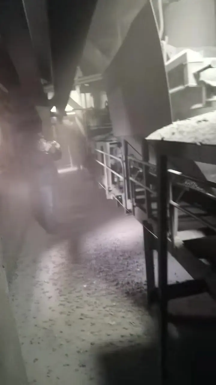
In heavy industries such as modern cement clinker preparation, coal handling systems of thermal power plants, mineral processing plants of metal mines, iron and steel metallurgy and coking, and bulk cargo transfer terminals at ports, belt conveyors are the core link that sustains high-throughput material movement across the whole plant. However, in the transfer chute and loading zone (Transfer Chute & Loading Zone) where material is transferred between lines, the high-drop fall and high-speed impact of bulk solids have always been the most severe source of dust pollution and the most frequent area of material spillage and leakage along the entire conveying corridor.
In the cement production process in particular, clinker after kiln discharge and cooling is an extremely dry, relatively hot, non-cohesive loose material with a very high content of fine powder particles. Because many older plants were constrained at the initial design stage by limited available headroom, the chute between the receiving hopper and the receiving belt is short, steep and mostly arranged as a vertical straight drop, and the interior of the chute has neither a speed-controlling curved surface nor any buffering, guiding or damping facility. When clinker pours at extremely high initial velocity onto the receiving conveyor belt, the kinetic energy released by the height difference is instantly converted into violent turbulent air surges and dust ejection. The site is not only accompanied all year round by deafening steel plate impact noise, but huge quantities of fine clinker powder also erupt outwards violently through the side gaps and the inlet and outlet openings of the skirt chute, depositing dust tens of centimetres thick on the floor and reducing visibility in the conveying corridor to an extremely low level.
Such severe dust dispersion not only directly breaches the environmental red line of national ultra-low emission requirements and accelerates mechanical wear of nearby bearings and gear reducers, but long-term suspension of fine particles also brings serious pneumoconiosis risks to the respiratory health of on-site inspection workers. For a long time, industrial sites have relied mostly on "blindly increasing the extraction volume of the downstream dust collector" or "frequent manual water spraying". For cement clinker, however, which absorbs water readily and hydrates and cakes easily, water spraying is tantamount to drinking poison to quench thirst and very easily causes the discharge opening to become sticky and completely blocked; while blindly increasing fan power not only causes electricity consumption to soar, but also leads to large quantities of qualified fine powder being extracted and lost and to rapid wear and perforation of the dust collector filter bags.
Therefore, starting from multiphase fluid mechanics and particle rheology, identifying the physical generation mechanisms of dust at transfer points and building an environmental ultra-clean sealing and dust-suppression integrated management system composed of "source-level fluidised curved speed control + full-section elastic buffering support + dual-lip self-sealing plenum containment + pressure-relief micro-negative-pressure capture" has become the inevitable path for green bulk material conveying in modern industry.
I. Systematic Deconstruction of the Fluid-Mechanical Mechanisms of Dust Escape from Transfer Chutes and Skirt Chutes
The dust ejection produced by bulk solids at a transfer point is not a simple splashing of material, but a series of coupled physical processes of gas-solid two-phase flow dynamics:
1. Free-fall Induced Air Mechanism and Positive-Pressure Plenum Effect
When bulk material falls from a height in a gravitational field, the material stream is not a continuous solid but a loose porous medium composed of countless discrete particles. According to the aerodynamic drag law, the surface of the falling material particles exerts a continuous viscous friction and shear drag force on the surrounding stationary air:
- In the course of falling, the particle stream acts like a natural "air pump", drawing large volumes of surrounding air into the interior of the material stream and forcefully pumping it downwards in the same direction, forming a high-speed downward induced air flow;
- Let the material drop height be ; the vertical falling velocity of the material particles when they contact the receiving belt can reach . If the vertical drop is 3.0 metres and the incoming belt has an initial parabolic horizontal velocity of 1.0 m/s, the resultant velocity at the instant the material touches the belt will exceed 5.0 m/s;
- When this high-speed particle stream carrying thousands of cubic metres per hour of air strikes the flat, enclosed receiving belt violently, the high-speed downward dynamic pressure is instantly obstructed by the wall and converted inside the enclosed skirt chute into an extremely high local static pressure (positive-pressure zone). The high-pressure air seeks out every weak gap and jets outwards at high speed, forcibly carrying the suspended ultrafine dust out of the skirt chute in the form of air jets.
2. Shear-Breakage Shock Waves and Elastic Rebound Jets
The hard material falling at high speed undergoes violent elastic and inelastic collisions with the receiving conveyor belt and idlers. High-speed impact not only causes secondary breakage and grinding of the particles themselves, producing more micron-scale fine powder, but the impact reaction force at the moment of collision also forces the air in the interstices between material particles to be instantly compressed and burst out, forming a horizontal shear airflow similar to a small "shock wave" that blows the fine dust radially outwards.
3. Turbulent Dust Generation Caused by the Velocity Vector Difference () between Material and Conveyor Belt
In a conventional straight-drop chute, the falling direction of the material stream is almost perpendicular to the horizontal receiving conveyor belt (the angle between the two approaches 90°). The receiving belt moves forward horizontally at 1.5–3.15 m/s, whereas the material has only a downward velocity and no horizontal velocity component. A huge velocity vector difference exists at the instant of contact. The material must be accelerated to belt speed within a short time by severe sliding friction on the belt surface. This violent relative sliding and rolling of the material layer completely destroys the laminar state of the material pile, causing severe material rolling, turbulent dust generation and lateral spillage from the frame.
II. Reflection on the Core Drawbacks of Conventional Transfer Chute and Skirt Chute Dust-Control Design
A deeper analysis shows that the reason conventional designs cannot control dust lies in the fact that conventional structures violate the laws of fluid mechanics:
1. Vertical Undamped Material Drop and Rigid Direct Impact
The interior of a conventional box-type vertical chute is completely open, and the material is subject to no speed limitation whatsoever under gravitational acceleration. The material strikes the skirt chute bottom plate or the conveyor belt directly, accompanied by intense structural vibration and noise, which not only accelerates the spalling and cracking of the belt cover rubber but also creates the largest induced air volume and impact air pressure in the entire process.
2. Wavy Fluctuation across Idler Gaps Causes Permanent Failure of the Sealing Skirtboard
The receiving area beneath a conventional skirt chute is usually supported by ordinary troughed idlers or rubber impact idlers. A structural spacing of 100 mm to 200 mm inevitably exists between idlers. When large lumps fall periodically, the conveyor belt undergoes severe sagging deformation and high-frequency wavy up-and-down fluctuation between adjacent idlers. The anti-spill skirtboard fixed to the side wall is straight; once the belt sags and sinks, an enormous dynamic gap of several centimetres instantly opens between the skirtboard and the belt; when the belt springs back up, it presses hard against the skirtboard. This high-frequency relative motion wears through or tears the conventional single-layer skirtboard within a few weeks, and the seal becomes completely nominal.
3. Imbalance in Extraction and Dust Collection System Design (Dust Collection Overload and Negative-Pressure Short Circuit)
Many enterprises attempt to suppress dust by installing high-volume dust collection fans, but neglect flow-field balance:
- If the inlet and outlet openings and the side gaps of the skirt chute are not strictly isolated, high-power extraction will only draw large volumes of cold outside air in from both ends of the skirt chute (forming a "false negative-pressure short circuit"), while the true high positive-pressure zone at the material drop core still ejects dust outwards;
- An excessively high extraction velocity (above 2.5–3.0 m/s) directly draws normally flowing, valid finished fine powder into the dust collector, which not only causes direct material loss through fly-off but also severely overloads and blinds the dust collector filter bags and rapidly wears through the elbows of the extraction ducting, causing air leakage.
III. Fluidised Reconstruction of the Curved Dust-Suppression Chute Based on EDEM Discrete Element Simulation
The core philosophy of modern advanced dust-suppression management is "suppress the air at the source and focus on guidance". Three-dimensional modelling and EDEM (Discrete Element Method) discrete element simulation software are used to simulate the real flow trajectory of the material and to carry out a spatial curved profile reconstruction of the conventional material drop chute, reducing the induced air and impact kinetic energy at the source by more than 70%:
1. Curved Fluidised Profiling and Smooth Kinetic Energy Control
- Profile-following smooth transition: the conventional right-angle bends and vertical straight-drop box bodies are eliminated, and a smoothly transitioning spoon-shaped curved chute is designed according to the material parabola. Through friction on the guiding curved surface and self-steering guidance, the vertically downward kinetic energy formed by gravitational acceleration is gently converted into horizontal kinetic energy consistent with the forward direction of the receiving conveyor belt;
- Velocity and direction matching: when the material slides out along the inner wall of the chute, its horizontal velocity vector almost completely matches the speed of the receiving belt (velocity vector difference ), and the material flow falls gently and tangentially onto the conveyor belt at a very small angle (≤15°). Vertical impact of material onto the belt, severe sliding friction and material splashing are completely eliminated, and the amount of induced air generated drops precipitously.
2. Static and Dynamic Material Cushion Self-Energy-Dissipation and Damping Technology
At the contraction and turning corners of the chute, material accumulation and flow-intercepting ridges are scientifically arranged, so that a controlled "material cushion" forms spontaneously inside the hopper by virtue of the material's own angle of repose. Subsequent falling material releases its energy on the cushion in a "material-on-material" manner, completely avoiding direct rigid impact of material on the metal steel plates, eliminating the risk of impact cracking of the equipment and reducing operating noise by more than 15 to 20 decibels.
Environmental Ultra-Clean Sealing System
IV. The Five Core Functional Modules of the Environmental Ultra-Clean Sealing System and Their Synergistic Mechanisms
To lock the residual fine dust completely inside the conveying line, a spatially tight and closed ultra-clean sealing system must be built in the receiving belt section. The system mainly consists of the following five core modules:
1. Skirt Chute Assembly Unit (Large-Volume Expansion and Fluid Pressure Stabilisation)
- High-rigidity heightened box body: modular thick-walled structural steel is precisely cut and assembled, and the overall cross-section is significantly heightened and widened to form a large-volume settling and pressure-stabilising plenum. When the induced airflow rushes from the narrow chute into the wide skirt chute, the flow cross-sectional area suddenly increases by 3 to 5 times, and the airflow velocity drops spontaneously and proportionally;
- Quick-release inspection top cover: the top is equipped with high-strength lightweight inspection cover plates with self-locking handles and quick-opening observation windows, and high-elasticity foamed silicone rubber sealing strips are used all around, achieving 100% airtightness with no air leakage while making daily inspection extremely convenient.
2. Dual-Layer Self-Sealing Skirtboard Unit (Two Lines of Defence for Precise Dust Locking)
- Inner polyurethane wear-resistant material-retaining plate: pressed tightly against the steel side wall inside the skirt chute, with high hardness (above Shore 85A), its bottom kept at a small clearance of 3–5 mm from the belt, specifically intercepting the lateral impact and squeezing of large ore lumps and clinker;
- Outer composite high-elastic dual-lip sealing strip: formed by co-extruding natural wear-resistant rubber and polyurethane in one piece. The primary and secondary sealing lips fit closely against the upper surface of the conveyor belt. The primary lip blocks overflowing fine-particle material, while the secondary lip, relying on micro-negative pressure and its own weight, hugs the belt surface to form a mirror-grade sealing isolation band against micro-dust; together with an external compression linkage, the skirtboard can be adjusted with stepless downward self-compensation by a single person without tools after wear.
3. Heavy-Duty Impact Bed Unit (Full-Section Elastic Stiffness Support with Zero Sag)
- Elimination of idler gaps: the original impact idler sets in the material drop section are completely removed and replaced by fully laid heavy-duty high-damping impact slider bars, made by hot-vulcanisation bonding of an ultra-high-molecular-weight polyethylene (UHMWPE) low-friction sliding surface with a highly elastic natural energy-absorbing rubber layer;
- Continuous seamless surface support: a flat, continuous slide support is provided for the conveyor belt directly beneath the skirt chute, so that the belt produces no sagging or local bouncing at all when subjected to large impacts, providing a constant and flat sliding reference surface for the dual-layer sealing skirtboard and permanently reducing the skirtboard air-leakage clearance to zero.
4. Multi-Stage Labyrinth Self-Damping Flow-Guiding Curtain Unit (Airflow Resistance Speed Reduction and Damped Settling)
Inside the skirt chute, along the direction of material travel, several split finger-shaped damping dust curtains made of highly wear-resistant natural rubber are hung in a staggered arrangement. The comb-tooth structure at the lower part of each curtain divides the long, narrow skirt chute into a series of cascaded small plenums with slight airflow resistance without hindering the smooth passage of material. Each time the high-speed dust-laden airflow passes through a curtain, its dynamic pressure undergoes a violent shear attenuation, and the airflow velocity rapidly decays below the critical velocity for free particle settling (< 0.5 m/s), so that the fine dust settles naturally back onto the surface of the material layer under gravity.
5. Plenum Micro-Negative-Pressure Relief and Dust Extraction Interface Unit
- Dynamic-pressure self-balancing relief channel: a vertical pressure-relief ventilation circulation pipeline is installed above the front section of the skirt chute where the positive pressure of material dropping is most intense, using the pipeline impedance to release the positive-pressure peak automatically;
- Precise tuning of the micro-negative-pressure dust extraction interface: the dust extraction suction inlet is located in the settling zone at the middle and rear part of the skirt chute where the airflow is completely stable. The system requires only an extremely small suction volume (about 30%–40% of the airflow volume of a conventional design) to establish a stable and weak negative-pressure barrier (-10 Pa to -30 Pa) inside the skirt chute, which ensures a slight inward inflow of surrounding air into the chute with no dust escaping, while never extracting qualified fine powder.
V. Full Performance Comparison Matrix of the Ultra-Clean Sealing Dust-Suppression System and Conventional Treatment Solutions
The table below provides a systematic quantitative comparison of the key engineering indicators of different dust-suppression technical solutions for bulk material transfer points:
| Evaluation dimension and performance indicator | Conventional vertical chute + ordinary single-layer skirtboard | Extraction-only high-volume dust collector solution | Environmental ultra-clean sealing system (integrated solution) |
|---|---|---|---|
| Impact kinetic energy of material at the transfer point | Vertical free-fall direct impact, high impact force, noise above 95 dB | No improvement in vertical impact, accompanied by strong machine vibration and structural fatigue | EDEM curved speed control with tangential downstream flow, impact force reduced by more than 80%, noise < 75 dB |
| Induced air generation and positive-pressure escape | Dynamic pressure rises sharply, severe dust ejection and dust blowing over the full cross-section along the line | Large volumes of outside air drawn in as a short circuit, local dead zones still ejecting dust under positive pressure | Induced air reduced by 70% at the source, multi-stage curtains for speed reduction and damping, the whole line locked under micro-negative pressure |
| Service life of the sealing skirtboard | Severe wavy belt fluctuation, extremely fast skirtboard wear (worn through in 1–2 months) | No improvement in skirtboard fit, deformation under lateral pressure causes frequent material leakage and tearing | Flat continuous surface support from the impact bed, service life of the dual-lip self-compensating skirtboard extended to more than 12 months |
| Material fly-loss and product loss | Large amounts of external spillage and dust accumulation along the line, spillage and leakage material loss of 0.5%–1% | Excessive airflow velocity forcibly extracts qualified fine powder, high product recovery loss | No external spillage or leakage, natural fall-back in the settling zone, material recovery rate above 99.9% |
| Overall system power consumption | Low baseline power consumption, but extremely high later costs for manual digging-out and water washing | Extremely high dust collector fan motor power (normally 45–75 kW running at high load) | Only a small auxiliary micro-negative-pressure exhaust is required (only 11–18.5 kW), saving more than 60% of plant energy |
| Environmental compliance of the inspection workplace | Dust in the corridor seriously exceeds limits (TSP generally > 50–100 mg/m³) | Local improvement but extremely high maintenance frequency, filter bags frequently worn and blocked | Airborne dust concentration stably controlled within the national ultra-low emission standard (TSP < 5 mg/m³) |
VI. Standardised On-Site Engineering Installation, Commissioning and Long-Term Maintenance-Free Operation and Maintenance Specifications
To ensure that the environmental ultra-clean sealing system delivers its ultimate effect of no dust, no spillage and no manual clean-up over the long term, on-site engineering implementation, operation and maintenance must strictly follow the procedures below:
1. Precise Geometric Calibration of the Impact Bed and Skirt Chute
- Flatness calibration of the impact bars: when installing the heavy-duty impact bed, a spirit level and a laser alignment instrument must be used to verify the elevation and coaxiality of the upper plane of the slider bars. The surface of the slider bars must transition smoothly with the empty conveyor belt on both sides, and the lateral and longitudinal flatness error must be strictly controlled within ±1.0 mm to avoid local stress concentration;
- Safety clearance between side guards and belt: the bottom edge of the metal side guard plates of the skirt chute must maintain an even, symmetrical physical safety clearance of 25 mm to 35 mm from the conveyor belt surface, strictly preventing deformation of the frame under load from causing the metal plates to rub directly against and score the belt surface.
2. Pressure Adjustment of the Dual-Lip Self-Compensating Sealing Skirtboard
- When installing the skirtboard, it must be pressed tightly in the direction of conveyor belt travel. The inner polyurethane hard material-retaining plate is adjusted to a 3 mm clearance above the belt; the outer rubber soft sealing lip is given an even slight pre-tightening force so that it bends slightly outwards to form an elastic contact surface. Excessive eccentric squeezing force must be strictly avoided, as it would increase the no-load load on the motor.
3. Air Volume Balance under Micro-Negative Pressure and Fine Adjustment of the Dust Extraction Butterfly Valve
- During the material feeding trial run, a portable micro-manometer and a hot-wire anemometer should be used to measure the actual internal micro-pressure difference at the inspection opening of the skirt chute. The manual regulating butterfly valve of the dust extraction branch pipe should be finely adjusted so that the working pressure inside the chute is precisely locked between -15 Pa and -25 Pa;
- Observe the airflow direction at the inlet and outlet openings of the skirt chute and ensure that the feed end and the discharge end are in a state of slight inward air intake, completely blocking any possibility of micro-dust jetting outwards.
4. Daily Inspection and Tool-Free Long-Term Maintenance Procedures
- Monthly visual inspection: observe through the transparent observation window whether the internal dust-suppression curtains are folded over or caught by long debris; check the wear allowance of the multi-stage impact slider bars, and turn them over or replace them in good time when the UHMWPE layer wears close to the limit line;
- Skirtboard self-compensating downward adjustment: when it is observed externally that the contact force of the secondary lip has weakened, it is only necessary to release the pressure lever of the quick-fit clamp and push the positioning slider gently downwards by hand to restore a constant sealing specific pressure. The whole process is a single-person operation requiring no welding, hot work or tools.
By completely abandoning the extensive mode of "vertical direct impact of falling material, single-layer dust leakage of the skirtboard, and violent extraction by a large dust extraction fan", reconstructing the material flow with EDEM curved speed control and solidifying the boundary with high-rigidity ultra-clean sealing, heavy-industry bulk material conveying systems can achieve the essential safety leap from "heavy pollution with spreading dust" to a green and clean state of "no dust in the gallery, no material accumulation under the machine, and no noise on site".