
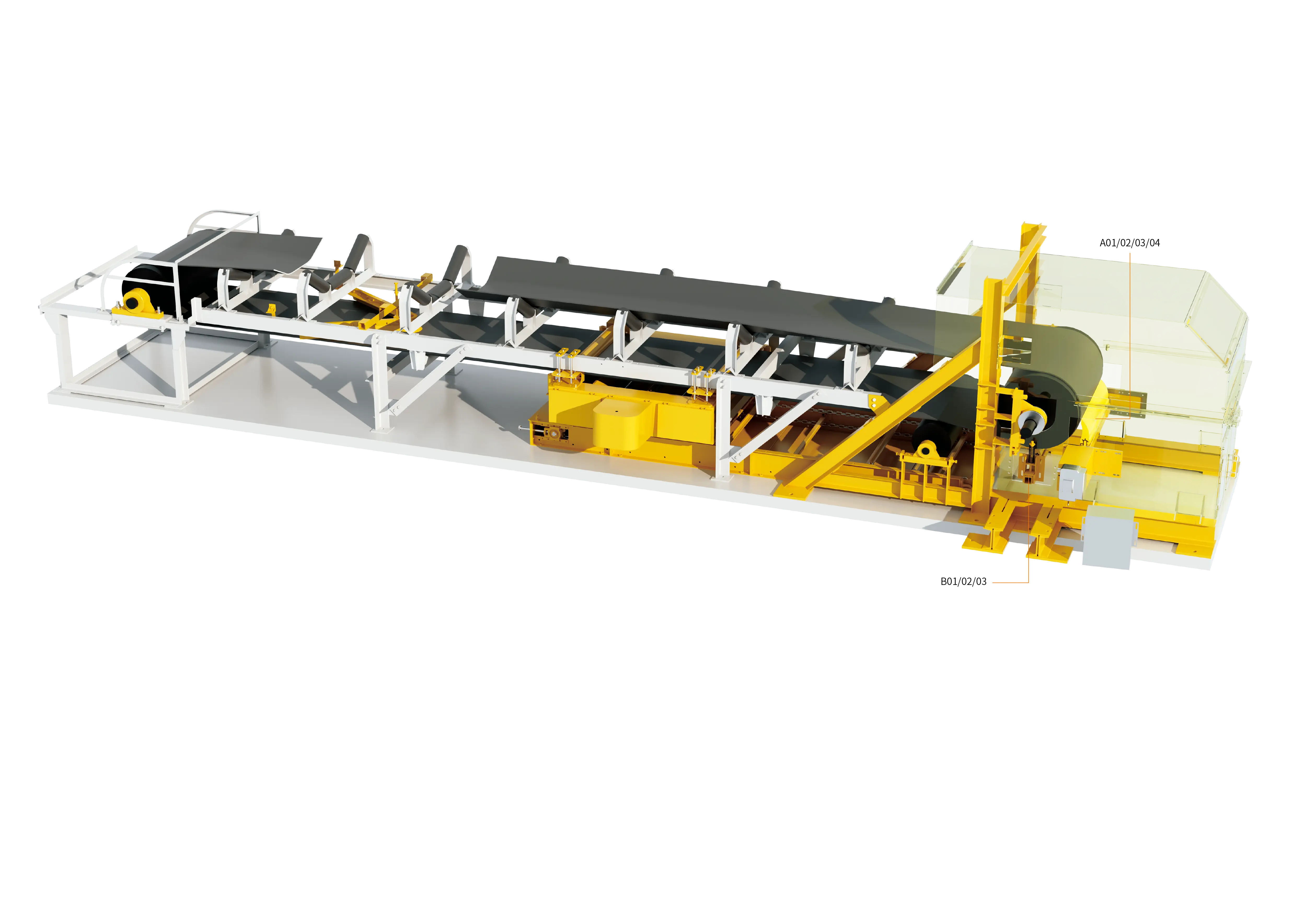
In coal mines, coal preparation plants, coal handling galleries of thermal power stations, mineral processing workshops of metal mines, cement clinker bases and bulk cargo terminals, belt conveyors carry out the high-frequency transport of thousands of tonnes of material along main bulk material transfer lines. Under ideal operating conditions, the bulk material on the conveyor belt should be completely released into the receiving chute at the discharge pulley under the action of centrifugal force and gravity. Under actual operating conditions, however, because materials such as coal, ore fines, wet mud and limestone generally have relatively high moisture content, ultrafine particle fractions and strong surface adhesion, a large number of particles remain firmly attached to the working surface of the belt after discharge and travel with the belt into the lower return strand, forming the highly harmful carryback phenomenon in industrial operation and maintenance.
Carryback is not only a huge waste of material through spillage and leakage, but also brings a chain of equipment disasters to the entire conveying corridor: the adhering material scales and hardens on the surfaces of the lower idlers, bend pulleys and snub pulleys along the route, changing the roundness of the pulley outside diameter and causing severe belt misalignment, intense local wear and even edge tearing; material that falls off over time accumulates like a mountain in the gallery below the conveyor, greatly increasing the labour intensity of manual cleaning, while the raised dust further induces serious hidden risks of dust explosion and environmental non-compliance.
Traditional countermeasures often remain at the stage of crude scraping with a single blade, yet the scraped wet and sticky debris piles up into a mountain below the head station and still requires workers to bend down periodically and shovel it out for removal. Therefore, modern high-efficiency conveying systems must adopt an integrated cleaning and recovery solution that deeply combines staged scraping (a multi-stage cleaner system) with enclosed collection and lifting (a chain-plate material recovery device).
I. Formation mechanism of carryback and its damage chain to conveying equipment
The adhesion of bulk material to the belt surface is not simple geometric sticking, but a physical-mechanical process jointly dominated by the capillary tension of the surface liquid film, electrostatic attraction and van der Waals forces:
1. Interfacial capillary water-bridge effect and adhesive hardening
Fine-grained ore powder or pulverised coal is subjected at the receiving section to gravity and compaction stress, and the moisture between particles is squeezed into the microscopic cracks of the belt rubber, forming tens of thousands of tiny capillary water bridges. After the belt passes around the head pulley and discharges, the fine ore powder that has not been released is firmly embedded in the rubber surface under the action of surface tension. As the return strand is exposed to the air, the moisture evaporates and the adhesive layer quickly air-dries and hardens into a dense crust.
2. Pulley fouling, deformation and violent belt misalignment
The belt carrying residual material is repeatedly squeezed against the lower idlers and bend pulleys, and the hardened sticky scale is gradually transferred and deposited in the middle or on one side of the pulley. This non-uniform fouling directly destroys the flatness and coaxiality of the pulley cylindrical surface and enlarges the local diameter. Under the traction of the belt speed, the belt is subjected to uneven forces and rapidly runs off at a large angle towards the side with thicker fouling, and may even fold over and tear.
3. Abnormal idler wear and sharply increasing energy consumption
When carryback passes over the surface of the return idlers, the highly abrasive ore particles are equivalent to high-hardness abrasive scattered between the idler shell and the belt, causing the metal idler shell to be worn through quickly or even to fracture, while the rotational resistance increases several times over, so that the drive motor of the whole machine runs overloaded for long periods.
II. Multi-level configuration of the staged belt cleaning system and technical analysis of each type of cleaner
A single cleaner cannot take care of both coarse scraping of large lumps and fine scraping of micro-dust. A conveying system with a high degree of cleanliness must build three progressive cleaning defence lines between the head discharge point and the return empty strand, according to spatial geometry and force characteristics:
1. Primary head cleaner (tangential coarse cleaning at the main discharge)
- Installation position: installed in the tangential arc region below the vertical centre line of the head discharge pulley where the belt separates (usually between 15° and 45° below the horizontal centre line of the pulley).
- Structure and material: mostly a segmented integral polyurethane blade structure, combined with a weight-type or pneumatic thrust tensioning mechanism.
- Functional characteristics: it directly meets the first belt surface after discharge and is mainly responsible for scraping off 80% to 90% of the thick adhering layer, lumps and high-flowability material stream on the belt surface, so that the scraped main material is thrown directly back into the main discharge chute along the tangential direction. Polyurethane material has excellent impact resistance and self-lubricating performance, and can effectively avoid mechanical belt fasteners without damaging the belt surface.
2. Secondary cleaner (micron-level fine scraping on the flat return run)
- Installation position: immediately behind the head discharge pulley, installed on the lower working face where the belt has just left the pulley and entered the flat section (usually at a distance of 200 mm to 800 mm behind the primary cleaner).
- Structure and material: carbide (tungsten-cobalt alloy / tungsten carbide) or ceramic-rubber composite scraper units. Each independent blade unit is equipped with an independent torsion spring, rubber torsion buffer seat or automatic pressure compensation mechanism.
- Functional characteristics: performs mirror-level fine scraping of the thin dense sticky mud, micro-crusts and stubborn deposits remaining after primary cleaning. The independent elastic compensation unit ensures that the blade follows the transverse undulations of the belt in real time, raising the removal rate of residues to more than 95%.
3. Return-run / V-plow cleaner (safety defence line for the non-working face)
- Installation position: installed in front of the tail bend pulley of the belt conveyor, or on the non-working face (upper surface) in front of the vertical weight tensioning device.
- Structure and material: symmetrically and diagonally arranged V-shaped (or inverted-triangle) rubber/polyurethane wear-resistant plough blades, floating and suspended on the frame crossbeam.
- Functional characteristics: specifically removes the scattered broken stone and foreign objects that fall onto the non-working face of the return strand along the conveyor due to material spillage and dust. Through V-shaped diversion the material is discharged to both sides of the belt, completely preventing hard gangue or iron pieces from being drawn between the bend pulley and the belt and causing the belt to be perforated and punctured.
4. Rotary brush and special cleaning devices
For high-inclination patterned conveyor belts, chevron anti-slip belts or aged belts with severe surface micro-cracks, rigid scraper blades cannot remove the coal mud trapped deep at the bottom of the grooves. In this case, an electric high-speed rotary roller brush (nylon/steel wire composite brush cleaner) is installed below the head station, driven by a motor to brush in the reverse direction at high speed, flicking the material accumulated in the grooves away at high speed.
III. Core structure and working mechanism of the chain-plate material recovery device
The fine material scraped off by the secondary cleaner usually has an extremely high water content and very strong stickiness, and owing to space constraints its falling position often deviates from the discharge opening range of the main discharge chute. If it is allowed to fall freely, a severe sludge accumulation zone will form below the head frame, eventually burying the idlers and supports. The chain-plate material recovery device is the core automated equipment that solves this chronic problem.
1. Structural assembly and layout form
As a whole, the chain-plate material recovery device presents itself as a low-speed, heavy-duty, fully enclosed miniature scraper conveyor, arranged compactly directly below the secondary cleaner (and rotary brush) at the conveyor head:
- Receiving hopper: shaped as a wide-opening funnel spanning directly beneath the secondary scraper blades, tightly receiving all the scraped wet sticky fine mud and scraping debris.
- Heavy-duty conveying trough and wear-resistant slideway: an enclosed chute welded from high-strength structural steel, with an ultra-high molecular weight polyethylene (UHMWPE) or wear-resistant alloy steel liner laid at the bottom, so that the friction resistance is extremely low and material sticking to the bottom is completely eliminated.
- Transmission chain-plate group and drive mechanism: a flameproof cycloidal pinwheel geared motor (or a hardened-tooth shaft-mounted gear reducer) drives a high-strength alloy die-forged chain, which in turn drives several thick-walled heavy-duty wear-resistant chain plates (scraper blades) in continuous slow circulation along the bottom of the trough.
2. Closed-loop return working mechanism
- Local scraping and collection: the fine wet material scraped from the working face of the belt falls directly into the enclosed recovery hopper, without leaking any dust or wastewater to the outside.
- Low-speed reverse lifting: under the constant traction of the geared motor, the chain plates push the viscous sediment along the trough bottom at a steady low speed and climb up along the upward-inclined casing.
- Re-injection into the main material flow channel: the discharge end of the recovery device extends directly into the main discharge chute of the conveyor or the next-stage transfer hopper. The material scraped and collected upward tips over and falls off at the discharge outlet, mixing again into the falling main material stream, completing 100% enclosed self-recovery of the material.
IV. Comparison table of technical characteristics and engineering configuration of cleaners and recovery equipment
To facilitate engineering selection and maintenance planning, the table below systematically summarises the performance parameters and functions of each core unit in the cleaning and recovery system:
| System unit category | Core material and structural principle | Optimal engineering installation position | Key control objectives and functional characteristics | Maintenance frequency and interval requirements |
|---|---|---|---|---|
| Primary head cleaner | Wear-resistant polymer polyurethane integral/split blades + elastic torque compensation | Tangential separation zone below the vertical centre line of the head discharge pulley | Coarse scraping of more than 80% of the thick material layer, with return material entering the main chute directly; avoids belt damage by fasteners | Inspect blade edge wear and preload every week; evaluate blade replacement every quarter |
| Secondary carbide cleaner | Tungsten-cobalt carbide/ceramic blade tips + independent one-way adaptive spring seats | Lower working face of the flat section after the belt leaves the head pulley | Fine scraping of residual dense sticky mud and micro-dust; cleaning rate above 95%, preventing mud carryback | Check blade flatness every month; periodically clean scale on the back of the blade holder |
| Return-run V-plow cleaner | Wear-resistant rubber/polyurethane V-shaped two-way plough blades + gravity floating suspension | Non-working face in front of the tail pulley or the vertical weight tensioning device | Intercepts scattered gangue debris falling on the upper surface of the return strand, preventing crushing and puncturing of pulleys | Check the contact gap of the plough blades every month; tighten and lower them promptly when wear exceeds limits |
| Rotary brush cleaner | High-speed flameproof motor + high-strength nylon/elastic fine steel wire cylindrical roller brush | Behind the secondary cleaner or on the bottom working face of patterned conveyor belts | Deep micro-pore brushing and material removal for patterned belts and aged belts with deep scratches | Check motor temperature rise and bristle collapse every week; periodically raise the brush disc height |
| Chain-plate material recovery device | Enclosed section-steel casing + die-forged high-strength alloy chain-plate scrapers + shaft-mounted gear reducer | Directly below the head secondary cleaner, with the discharge outlet extending into the main transfer chute | Collects 100% of the scraped wet sticky fine mud in an enclosed manner and automatically lifts it back into the main chute, eliminating manual cleaning | Check drive chain tension and pin lubrication every month; check bottom liner wear every six months |
V. Closed-loop interlocking control logic of "intelligent sensing + efficient scraping + automatic return"
To achieve unattended on-site operation and a high degree of self-healing in the conveying system, the cleaning and recovery system must be interlocked with the main conveyor through strict electrical control:
- Sequenced start-up and delayed shutdown interlocking logic
- Reverse pre-start: before the entire conveyor line starts, the PLC control system starts the chain-plate material recovery device first and lets it run for 5 to 10 seconds, so as to ensure that the interior of the recovery trough is unobstructed before the main belt conveyor is allowed to start.
- Delayed tail-end sweeping: after the conveyor stops and the power supply is cut off, the chain-plate recovery device must continue to run with a delay of 3 to 5 minutes until the residual material finally scraped off by the cleaners has been completely discharged into the main chute; only then is the power supply of the drive motor automatically cut off, avoiding material remaining in the trough that could cool, condense, cake and harden.
- Multiple protections against overload seizure and stalling The drive motor of the chain-plate recovery device is equipped with a highly sensitive current transformer and a thermal overload relay. If a large piece of tramp iron jams the chain plates and causes instantaneous stalling, the system automatically cuts off the power supply of the recovery machine and issues an audible and visual alarm within 0.5 seconds after the current exceeds the set value, preventing the motor from burning out or the transmission chain from being pulled apart.
- Anti-blockage interlock of the return discharge outlet A material level sensor is installed at the discharge hopper of the material recovery device. When blockage of the main chute due to full-bin conditions spreads to the recovery outlet, the recovery machine immediately stops automatically in an interlocked manner and reports a fault signal to the central control dispatching system, preventing secondary accumulation of material from bursting the casing.
VI. On-site standardised installation and commissioning, safe operation and long-term maintenance specifications
To ensure that the cleaning and recovery system achieves a long-term high cleaning rate, a low wear rate and zero manual digging, the following engineering work specifications must be observed:
- Precise calibration of scraper pressure and geometric contact angle:
- The contact angle between the polyurethane primary scraper and the outer diameter of the conveyor belt is usually controlled between 65° and 80° downwards in the tangential direction, avoiding a blunt-angle shovelling attitude greater than 90° that would damage the rubber surface of the belt.
- The linear pressure exerted by the secondary carbide scraper on the belt should be fine-tuned according to specifications (usually maintained at 1.5–2.5 kg/cm of width). If the pressure is too low, the cleaning effect cannot be achieved; if the pressure is too high, the blade tips will heat up severely, the rubber belt surface will peel and carbonise, and the no-load energy consumption of the belt conveyor will increase substantially.
- Specifications for chain-plate chain tensioning and track lubrication:
- Periodically adjust the tensioning screw at the tail of the recovery device to keep the chain sag within a reasonable range; the chain must never be so loose as to cause tooth jumping and rail gouging, nor so tight as to aggravate mechanical wear of the pins.
- Every quarter, add extreme-pressure lithium complex grease to the driving and driven bearing housings of the recovery machine, and clean the dust inside the drive roller chain guard.
- Strict compliance with the safety red lines for confined spaces and rotating machinery:
- It is strictly forbidden to put hands, feet or a shovel into the cleaner or the inside of the head guard to remove material stuck to the scraper while the belt conveyor is running.
- Any work involving replacement of cleaner blades or maintenance of the chain plates must strictly follow the lockout/tagout (LOTO) procedure with a dedicated supervisor on watch, completely eliminating casualties caused by illegal live working.
By scientifically implementing primary polyurethane coarse scraping, secondary adaptive alloy fine scraping, return-run V-plow safety protection and fully enclosed continuous chain-plate material return, heavy industry bulk material conveying lines can completely eradicate the chronic problem of carryback and build a clean, environmentally friendly, efficient and highly automated new normal for green conveying.
Learn about the intelligent cleaning and material recovery system solution